Electrical Geometry Management | ||
| ||
Segment Creation
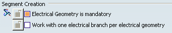
- Electrical Geometry is mandatory
- Select this check box to force the creation of an electrical geometry before any other action.
 By default,
This option is selected.
By default,
This option is selected.
- Work with one electrical branch per electrical geometry
- Select this check box to create only one electrical branch in an
electrical geometry. Doing so will optimize overall performance.
To take advantage of ENOVIA configuration management at electrical branch level, clear this check box.
The following table will help you understand how this option works depending on what you select and how far you have gone in your design.
If the option is... And... Then the Harness Bundle command... (no impact) No electrical branch exists Creates a new electrical branch geometry. Selected One electrical branch exists Edits the electrical branch geometry. No new electrical branch is created. Cleared Electrical geometry is activated Creates a new electrical branch geometry. (no impact) At least one electrical branch exists with one branch, but no geometry has been associated and no route defined and, nothing is selected in the geometry area. Edits the branch.
By default,
This option is not selected.
![]()
Segment Connection
- Electrical link driven by geometry
- Select this check box to create both a geometrical and an
electrical link between the selected segments or the selected
segment and device. If necessary, the segment is extended to make
the geometrical link.
If cleared, an electrical link only is created. Clearing this check box lets you create distant connections when the two selected objects are not geometrically linked.
Important: If Electrical link driven by geometry is not selected: The selection order during the creation of a distant link (electrical connection) is important: When you create a distant link, you change the electrical end from one segment to another. For example:
- Firstly, create a distant link from Segment A to Segment B.
- Secondly, a distant link from Segment A to Segment C. As a
consequence, the first link between A & B is replaced by the
new link, because an electrical connection cannot be located at two
locations.
- It is recommended to create a distant link from B to A.
- And then from C to A.
Symbols providing user feedback about connection status are as follows:
- No electrical connection:

- Electrical connection:

- Geometrically connected:

- Distant connection; No geometrical link:

Important: If you remove electrical links (unlink branches) and if this option is not selected, geometrical links cannot be maintained. For more information about the Connecting Segments command, please refer to the Electrical Harness Installation Guide.
By default,
this option is selected.
![]()
Branch Disconnection
- Branch Disconnection options
Specify how you want to manage unused branch points when a branch is disconnected or deleted. Select:
- Keep unused branch point to keep branch points
- Prompt user for deletion to make the system ask how you want to handle the branch segments after their deletion.
This choice applies when the:
- Branch point is removed from the route definition of the branch.
- Branch is unlinked from the branch point using the Disconnect command.
- Branch is deleted using Delete Special.
Tip: If branch points are used in an ENOVIA configuration, select the Keep unused branch point option to avoid unexpected deletion. For example, a branch point is used in different configurations and you are working on a resolved configuration that does not include the branch point.
By default,
The option is Keep unused branch points.
![]()
Segment Profile
- Any profile / Circular profile
- Select Any profile to manage individual segment profiles. When you create a segment, the rib is replaced by a loft representation. More or different options are available in the dialog boxes for Branch Definition, Segment Definition and Profile Management.
Select Circular profile to create round segments only.
By default,
Any profile is selected.
- Segment profile options
- Four options let you determine how section parameters will be updated when the profile area is directly modified or updated after conductor routing.
- Keep the greatest value constant
If this option is selected, the greatest value remains unchanged:
- For rectangular profiles, it is the greatest value between height and width.
- For ellipses, it is the greatest value between the major and minor axis.
The other value only is updated.
By default,
This option is selected.
- Automatically impose profile properties from segment connection point or cavity
- If this option is selected, the branch routed via the segment connection point or cavity will carry the section properties as / if defined in the segment connection point or cavity.
- If the option is not selected, the branch will be routed normally and will get the default section properties (circular, ...).
By default,
This option is not selected.
![]()
Segment Computation
- Allow system to use a smaller bend radius value
- In Standard algorithm mode, if Allow system to use a smaller bend radius value is selected, and the standard algorithm does not converge, the bend radius is optimized to keep the flexible curve.
By default,
This option is not selected.
- Standard algorithm
- If Standard algorithm is selected, the standard
algorithm is used to compute branches and give the best possible
branch shape.
- If the algorithm converges, a flexible electrical curve is generated.
- If it does not converge, a regular spline is generated.
By default,
This option is not selected.
- FLEX algorithm
If FLEX algorithm is selected, the FLEX computation algorithm is used to give a more realistic shape to segments. This option is only available if a FLEX Physical Simulation license is present.
- Balance between performance (P) and accuracy (A)
The slider allows you to choose the balance between calculation time (P) and accuracy (A).
By default,
The position of the slider is as shown above.
- Tolerance (%) in Constrained Length mode
This option is used for Constrained Length mode only.
The spinner lets you set a tolerance value: it represents the percent tolerance permitted between the initial and final segment length.
By default,
The value is 1 (Real type).
Notes: In mode, the default accuracy is set to a very high value in order to respect segment length better. The value set for the balance slider is not taken into account.
About the FBDI Import:
- The V5 Electrical Splice object aggregates the Length and Equivalent Thickness attributes. In V5, these attributes are used in the Flex algorithm to compute a realist form of the bundle containing it.
About Materials:
- You can define a Material using the Simulia Material Editor Workbench to apply the material on the segments and protections of an electrical branch geometry : Start > Infrastructure > Material Editor.
- Then, the Material will be taken into account in the Flex algorithm, the rendering of the Segment will be different and the properties of the Material are available.
For more information, please refer to Electrical 3D Installation User's Guide: About the FLEX Algorithm.
![]()
Feedback for Branch
- Warn user when branch is collapsed
- Select the Warn user when branch is collapsed check box to get a message when updating or modifying a branch if the computed bend radius is less than the segment diameter.
By default,
This option is selected.
- Avoid the repetition of warning message when building curve
- Select the Avoid the repetition of warning message when building curve check box to avoid the unnecessary warning messages that appear when building curve.
The warning messages will not be repeated if the curve is already built using Dichotomy algorithm or if the flexible curve is already broken.
By default,
This option is not selected.
![]()
Visual Feedback on Segment Curve
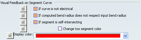
- If curve is not electrical
- Select If curve is not electrical to display the center curve of regular spline branches in the color set in the Display Color list. A warning is displayed: "The spline of the edited segment is a regular spline. In order to switch it back to an electrical curve, you may change one or more parameters value (bend radius...). NB: The computation failed between the two highlighted points."
- If computed bend radius does not respect input bend radius
- Select If computed bend radius does not respect input bend radius to display the center curve of branches whose computed bend radius does not respect the input bend radius in the color set in the Display Color list.
Important: After editing the Segment of a regular curve, if 2 red spots appear on the branch shape computation, it means that the standard algorithm (Bend Radius / Diameter) is not respected between these two points. For more information, please refer to About Routing, Branch Shape Computation, in the Electrical 3D Installation User Guide. - If segment is collapsed
- Select If segment is collapsed to display the center curve of branches whose computed bend radius is less than the segment diameter in the color set in the Display Color list.
By default,
All options, except Change also segment color, are
selected.
![]()
Protective Covering Instantiation
- Authorize from scratch mode
- Select the Authorize from scratch mode check box to define protective covering specifications directly when adding protective coverings to your segments.
By default,
This option is selected.
- Default line type
- Select the Default line type check box and then select a
value from the list to set the default line type used to represent
protective coverings on drawings for all protective coverings
created from scratch.
By default,
This option is cleared.
![]()
Visualization for Local Slack
- Display slack for all segments
- Select the Display slack for all segments check box to see where the slacks have been added in the entire electrical geometry, for all the portions of branches in design mode in the session, when the command Local Slack is activated. You no longer need to do it branch by branch via the Route Definition command, but you can have a quick and global view of the places where the slacks are added in the whole electrical geometry.
By default,
this option is cleared.
![]()
Collapse Node in Tree

- Collapse Electrical Geometry node when exiting Branch definition dialog box
- Select the Collapse Electrical Geometry node when exiting Branch definition dialog box check box to close the Electrical Geometry node in the specification tree on completion or
cancellation of the Branch Definition command. The
specification tree is collapsed up to the parent Electrical Geometry node. It
simplifies the tree view of the Electrical Geometry Tree structure.
By default,
This option is cleared.