Flattening Orientation | ||||||||
|
| |||||||
Click Harness Flattening Parameters
 .
.
The Harness Flattening Parameters dialog box opens on the General tab.
Select the Flattening Orientation tab:
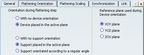
Choose the orientation of the device during the flattening step.
- By selecting With no device orientation, the device is positioned by a transformation computed by the flattening algorithm. However, there is no specific action on the orientation of the device and it will depend upon the selected active plane.
- If you select Device placed in the active plane, the local Z axis of the device is positioned perpendicular to the active plane specified in the General tab of this dialog box.
Choose the support orientation.
- By selecting With no support orientation, the supports will maintain their 3D orientation.
- If you select Support placed in the active plane, the support will be orientated with respect to the active plane specified in the General tab of this dialog box.
- Finally when choosing the third option, Support
orientated according to a regular angle, the default
orientation behavior of the supports keeps the real position
(angle between 0°
and 360°).
Supports will be placed according to the closest regular
angle they have in 3D. It enables you to prevent segments
from twisting. They are four regular angles (0°,
90°,
180°
and 270°).
0°: the angle will be applied if the real position is between -45° (or 315°) and 45°.
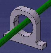
90° : the angle will be applied if the real position is between 45° and 135°.
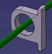
180°: the angle will be applied if the real position is between 135° and 225°.
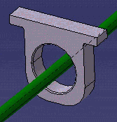
270°: the angle will be applied if the real position is between 225° and 315°.
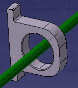
Specify the Reference plane used when the device was created. This same plane is used to orient the device when flattened.
The user can choose the orientation of electrical component during the flattening step without modifying the reference component. He can choose 3 standards planes: XOY, YOZ or ZOX. The XOY plane is selected by default.
Inside one electrical geometry, all devices must be created with the same orientation, because this option, Reference plane used during Device Orientation, is valid for all devices during flattening.
Click OK to validate.
The local references of the supports and devices are used to orientate the components. Thus the angle is calculated with the chosen axis of the part containing the support or device and the normal of the active plane.