Creating Wire Annotations | |||
| |||
Generating a Drawing
You can generate a drawing from the flattened geometry.
Click Front View
 .
.You are prompted to select a reference plane on the 3D geometry.
Click a plane in the flattened geometry document: for example the face of a connector. The drawing document updates according to this choice:
| Important: If you want to create a Drawing using View From 3D command; then make sure that General Parameters and the 3D Annotation Plane are in the same context, or use Customizing a Drawing View for specifying the Drawing Options. |
![]()
Creating Wire Annotations
You can add annotations on wire attributes.
In the Drafting workbench, click Wire Annotation
 .
.Two dialog boxes open:
-
The Tools Palette, which allows you to show or hide the wire annotation dialog box:
-
When it looks like this, the Wire Attributes dialog box is visible.

-
When it looks like that, the Wire Attributes dialog box is not visible. Click Tools Palette to make it visible.

-
-
The Wire Attributes dialog box, which allows you to select the attributes you want to see as annotations:
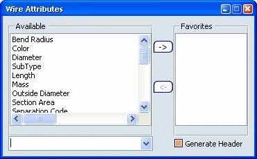
-
To add an attribute from Available to Favorites, select the attribute of interest, then click the right arrow
 .
. -
To remove an attribute from Favorites, select it in the list, then click the left arrow
 .
. -
By default, the last Favorites used are available when the dialog box is re-opened.
-
If you want to save different favorite lists: select the attributes needed, enter a name in the input field then validate. You can then display your favorite list in the list box.
-
-
Then, you can select a segment by clicking its 3D Projection or SingleLine, or select a connector by clicking the 3D Projection in the geometry.
If the connector is a 2D Detail, you cannot select it. But you should select the Segment Connection Point that is projected in the Drawing. For information, by using the Automatic Generation function, you can select the points more easily and create the Wire Annotations automatically.
A table is created, showing all the attributes that you have selected in Favorites.
If you want to add another wire annotation, you have to click Wire Annotation
again before selecting a segment or a connector.There is an automatic update of the modifications except if you remove or add some components.
If you want to customize the graphical representation of the table, right-click to display the contextual menu then select Properties.
Important: This command is not available for internal splices. Wire specifications do not have part numbers (the field in the conductor attributes table is left blank). A part number is assigned when a conductor reference is associated to the wire specification.