Generating Segment Arrangement View | |||||
|
| ||||
Open a product containing at least one support with several branches.
Select the Electrical Geometry in the flatten view.
For a better visibility, you can arrange branches at any junction to obtain equal angles by clicking Live Manipulator
 > Arrange Junction.
Select PLM Access > Drawing... from the menu bar to create a new Sheet.
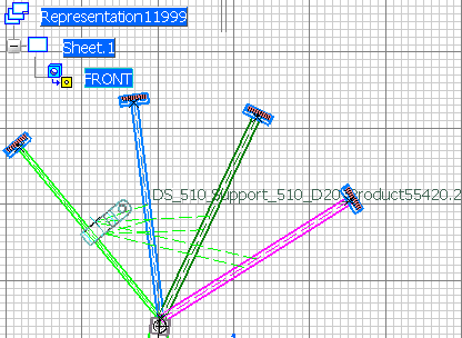
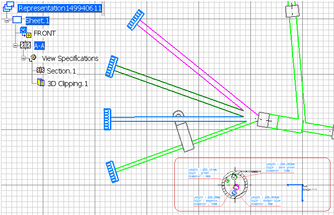
The Drafting workbench is loaded and an empty drawing representation is created. The first empty sheet, Sheet.1 is created. And the Electrical Dress-up toolbar appears:
Click Segment Arrangement View
 in the Electrical Dress-up toolbar (Drafting workbench) and select the support in the drawing.
When your cursor flies over a support, the support name is displayed:
When your cursor flies over any object but a support, a symbol is displayed to indicate that this action is forbidden. .
Click the sheet to select the position of the segment arrangement view.
For information, the segment arrangement view is based on the Drafting clipping box capability, by this way you obtain the exact frame of the support. You can also select the projection of a 2D Detail.
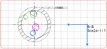
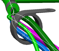
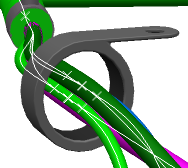
You can see the view of branch arrangement in support in the drawing
Notes:
- The segment arrangement view is based on the Drafting clipping box capability, by this way you obtain the exact frame of the support. You can also select the projection of a 2D Detail.
- In the segment arrangement view, the viewing direction depends on fork conditions. Please refer to More about Segment Arrangement View.
- Note that the segment color is reported on the drawing. To obtain this result, you need to select the Yes option of the Color setting in Tools > Standard Drafting > ViewDressUp > 3DInheritance > Wireframe.
To instantiate Text Templates on the segment arrangement view, double-click the segment view (B-B) to make it UI-active and click Automatic Generation
 in the Electrical Dress-up toolbar.
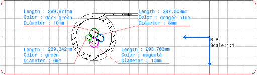
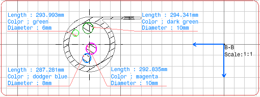
Text Templates are generated on the segments:
Notes:
- This Automatic Generation command will generate a Text Template on every support present in the drawing. Automatic Generation and Update Dress-up commands can be executed on all support section views. Moreover the section view will be generated for all the sections defined in the support and no separate section view will be generated per support section.
- Multi-profile definition of segments (circular or rectangular) can be considered in the support section view.
In the drawing, the final result is:
The next steps will show you how the segment view is updated after modifying the segments' arrangement.
In the 3D view, select Tools > Segment Arrangement > Arrange Segments
 and select a support.
For more information, please refer to Electrical 3D Installation User's Guide: Arranging Segments in Supports.
In the geometry area, move the segments to the desired location inside the support.
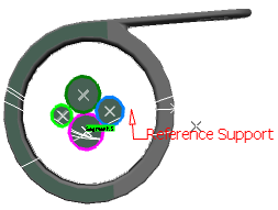
Click OK when done.
Update both the 3D product and the 2D representation.
You can see that the drawing view of segment arrangement has been updated: