Auto-Constraining a Group of Elements | ||||||
|
| |||||
Select the profile to be constrained.
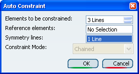
The Auto Constraint dialog box appears. The Elements to be constrained field indicates all the elements detected by the application after selecting the profile.
Click the Symmetry lines field and select the vertical line in the geometry area.
All the elements in the profile that are symmetrical to the Line will be detected.
Click OK to constrain the sketch including the profile and the vertical line and, if needed, modify the location of the constraints.
- Parallelism
- Symmetry
- Tangency
- Radius
- Angle (two constraints)
- Offset (two constraints)
The sketch is not displayed in green because it is not constrained in relation to external elements (edges, planes and so on).