What are Constraints? | |||||
|
| ||||
Geometric Constraints
A geometric constraint is a relationship that forces a limitation between one or more geometric elements.
For example, a geometric constraint might require that two lines be parallel. If you select three lines, or two lines and a point, these elements will automatically result parallel to each others, as illustrated in the table further down.
You can set a constraint on one element or between two or more elements.
| Number of Elements | Corresponding Geometric Constraints |
| One Element | Fix Horizontal Vertical |
| Two Elements | Coincidence Concentricity Tangency Parallelism Midpoint Perpendicularity |
| Three Elements | Symmetry Equidistant Point |
When creating a constraint, remember that:
-
A green constraint is a valid constraint by default.
-
Conversely, a yellow constraint indicates that the definition is not valid.
The software lets you customize the colors and more generally the style of the constraints you use. To have details about these capabilities, see the Sketcher customization section of this guide.
When you position the cursor on constraint symbols, the software calls your attention on the elements involved in the constraint system.
![]()
Dimensional Constraints
A dimensional constraint is a constraint whose value determines geometric object measurement.
For example, it might control the length of a line, or the distance between two points.
You will use Constraint
![]() to finalize your profile. The Constraint command allows you to
set dimensional or geometric constraints but you will mainly use it to set
dimensional constraints.
to finalize your profile. The Constraint command allows you to
set dimensional or geometric constraints but you will mainly use it to set
dimensional constraints.
You can combine dimensional constraints to constrain a feature or sketch.
You can set a dimensional constraint on one element or between two elements.
| Number of Elements | Corresponding Geometric Constraints |
| One Element | Length Radius/Diameter Semimajor axis Semiminor axis |
| Two Elements | Distance Angle |
You can apply a diameter constraint between two lines provided one of these lines is an axis line.
| Important: The application does not take into account negative values. |
![]()
What about Constraining While Sketching?
Provided you previously activated Constraint , sketching certain elements automatically generates constraints although you did not specify that you wanted these elements to be actually constrained.
![]()
Creating a Constraint Between a 2D and a 3D Element
When you need to create a constraint between a 3D element and a line, it may result impossible. You will therefore have to use manually the projection operators.
When you need to create a constraint between a 3D element and a line, for example, this creation may result impossible. This is the case when the projection or intersection resulting use-edge does not give a unique solution. In other words, the use-edge (projection of one side of a pad) corresponds to several limit edges of the side.
As a result, you will not be able to select this 3D element when creating the constraint. You will therefore have to use manually the projection operators.
![]()
What is SmartPick?
SmartPick is an intuitive, easy-to-use tool designed to make all your Sketcher creation and edition tasks as simple as possible.
SmartPick dynamically detects the following geometric constraints:
- support lines and circles
- alignment
- parallelism
- perpendicularity
- tangency
- concentricity
- horizontality and verticality
- midpoint
![]()
Constraints and Geometrical Supports
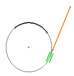
When you apply constraints on curves, lines, circles and ellipses, the complete geometrical support is taken into account.
In the example below, SmartPick is active as you are creating a line. This capability detects a coincidence constraint between the line and the support of the arc.
