Select .
In the Printer List area, right-click the printer to be configured then select
Configure (or double-click the printer
name):
The capture above takes a 3D PLM Printer as an
example.
If you add a Windows printer, the properties dialog box
displays standard setup parameters corresponding to the selected
printer type. See your Windows documentation for
detailed information about this dialog box.
In the Printer Properties dialog box, modify the necessary data.
See Adding a Printer
for more information about printer properties.
Click
Advanced Configuration... to configure the CGM driver:
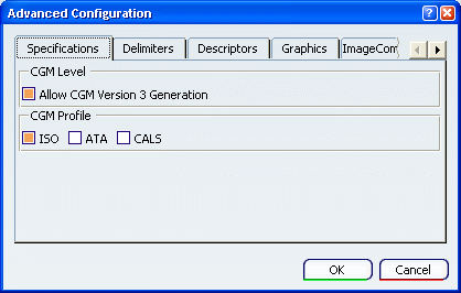
In the Advanced Configuration dialog box, access the Specifications tab then select the
appropriate options:
- Allow CGM Version 3
Generation lets you generate CGM Version 3.
- ISO: CGM is a graphic format defined by the International
Standards Organization ISO/IEC 8632:19999.
- ATA (Air Transport Association):
part of the ATA Specification 2100.
GREXCHANGE, for technical documentation of the manufacture and
operation of commercial airplanes, supports the binary
and clear text encodings at the CGM Version 3 functionality
level. It is appropriate for the exchange of technical manuals,
publishing applications, and visualization.
IGEXCHANGE provides for the transfer of intelligence associated
with graphical data. This profiles supports the application
structuring defined in CGM Amendment 2.
Both profiles are developed and maintained by the ATA/AIA
(Airline Transport Association and Airline Industry Association)
- CALS (Continuous Acquisition and Life-Cycle
Support): part of the CALS family of standards which is
an initiative of the U.S. Department of
Defense for technical illustrations and publications.
This profile supports the binary encoding at the CGM Version 3
functionality level.
Access the Delimiters tab then define the
necessary parameters:
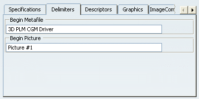
- Begin Metafile: all CGM files start with the same identifier,
BEGIN METAFILE, and you can enter the data to be used as
identifier. The default is "3D PLM CGM Driver".
- Begin Picture: sets the default state the CGM interpreter
will return to at the beginning of each new picture. The default
is "Picture #1".
Access the Descriptors tab then select the
appropriate options:
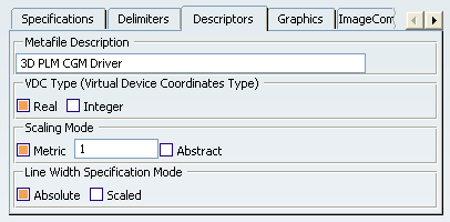
- Metafile Description: enter the description text to be used
for the metafile (e.g. author, date, version, etc.).
- VDC Type: Specify the type of coordinates for the metafile,
either Real or Integer.
- Scaling Mode: select the mode to be used by activating the
corresponding option.
- Metric: lets you enter the
physical size of the CGMs in millimeters.
- Abstract: CGMs are
dimensionless (they do not have an actual physical size you can
measure in pixels, inches, etc.). In that case, Virtual Device
Coordinates (VDC) are used as units of measure.
- Line Width Specification Mode.
- Absolute: the line
width is measured in VDC units.
- Scaled: the
line width on the printer is automatically scaled to the
screen line width set as a scale factor to be applied to a
device-dependent nominal line width.
Access the Graphics tab:
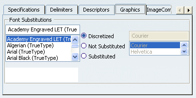
In the Font Substitutions list, select
a font then set the property of your choice by selecting the
appropriate option:
- Discretized: when the image suffers from
a lack of points, points are distributed to fill the gaps and
ensure linearity.
- Not Substituted: the font is kept as is,
it is not replaced by any font.
- Substituted: lets you replace the selected font by
a suitable replacement font you select in the list displayed to
the right of the options. This list is activated as soon as the
Substituted option is selected.
Access the Image Compression tab then select the appropriate options:
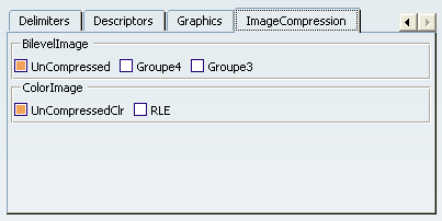
BilevelImage refers to black and white image. ColorImage refers to 3 RGB components color images. For more information about Image Compression, see .
Click OK to validate and close the
Advanced Configuration dialog box.
Click OK to close the Printer Properties
dialog box.
The printer configuration
file ($HOME/CATSettings/Printers/PLOTxxxx.xml) is
modified.
Access the printer configuration file then open it:
Your modifications have been written in XML format in the file.
Note that a .dtd file containing the description of
the XML configuration file is
provided in:
C:\Program Files\Dassault Systemes\Bn\intel_a\resources\printerDTD\printer.dtd
where "n" is the current release number and "OS_a" is your operating system (e.g. aix_a, hpux_b).
Re-select the advanced configuration settings to check
that your modifications have been taken into account.