Changing a Context

You can change a context in Part Design edition.

Important:

  • Change context behavior allows you change location in an assembly structure in order to reach a desired geometry.

  • Change context behavior takes into account flexible assembly context (Positionable Mechanical Reference) and the repositioning of flexible assembly instance. Information about minimum rigid context, minimum flexible context is displayed in the Edit Links & Relations dialog box and when you change the context. A change context is also made when you make a first contextual import in a Part feature, a minimum flexible context is made. During the second contextual import the context can be modified.


Before you begin: Open an existing product containing 3D shapes with links and relations between them.
Related Topics
About Links and Relations
Edit Links and Relations Dialog Box
  1. Edit Pad.1 of a context 3D Part.

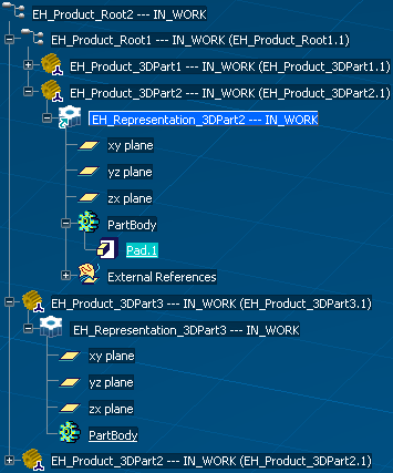
    The Part representation icon in the Specification Tree displays a green arrow .

  2. In the Pad Definition dialog box, select Up to Plane as First Limit type.

  3. Select the xy plane of EH_Representation_3DPart3.

    The Change context dialog box appears.


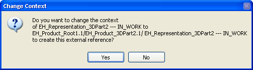
    Important:

    When no context or too many context have been found a specific warning message is displayed in the Change context dialog box.

  4. Click OK in the Change context dialog box.

    The EH_Representation_3DPart2 context has been changed, the Representation icon in the Specification Tree displays a green diamond as minimal context .