Open a document with geometrical data.
In this scenario, we use a product with two part bodies containing
at least one pad each:
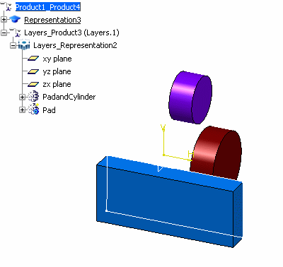
You can see clearly that the two features are
named PadandCylinder and Pad.
Select :

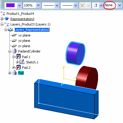
In the Graphic Properties toolbar, the Layer
list indicates the current layer (if no objects are selected) or
the layer of the selected object.
None indicates that
there is no current layer, which guarantees that all the contents
of your document are visible. You can assign objects to None:
any object assigned to None is always visible.
Double-click a representation to switch to a part
edition context.
Select a part body in the tree (PadandCylinder in
our example), click the arrow
on the Layer list, then select 0 General from
the list.
PadandCylinder is
assigned to the layer 0 General.
The Layer
list now looks like this:
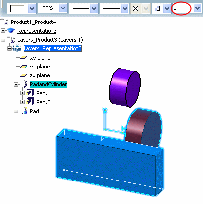
You see only the number because all layers are identified
primarily by their number.
Select the different features in the part body (e.g. Pad.1
and
Pad.2):
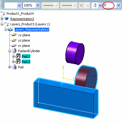
These features are located on the layer 0
because they inherit the layer of the part body (PadandCylinder).
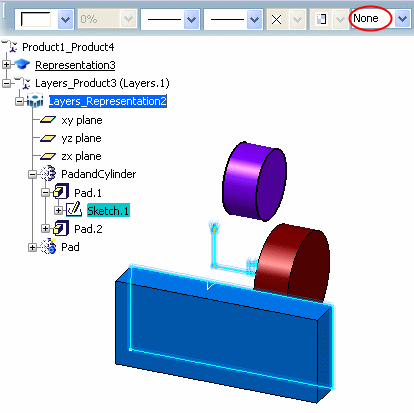
This time, still in the part body (PadandCylinder), select any of
the sketches.
The sketches from which the
features are built remain on the current layer None:
Select another part body in the tree (e.g. Pad).
Pad is still located on the current layer:
Optional: To change the
current layer, first make sure no object is selected, then enter the
layer number in the list.