Importing Panels | ||||||
|
| |||||
Select PLM Access > Import > File...
The Import from file dialog box opens.
Select the IDF file containing the panel data you want to import.
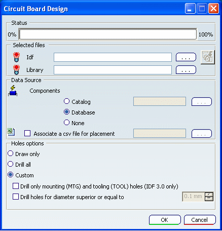
The Circuit Board Design dialog box opens:

Note: An IDF file contains the description of one panel or one board only. If the panel import file also refers to a board, the board part number is indicated in the file and Edit Links becomes available allowing you to find the board and components. The board and components can be imported either from the database or via IDF files.
To import components, do one of the following:
- To import components from the database, select an IDF file only.
By default, the Database option under Data Source is selected and component geometry is About IDF Files.
- To import components from the catalog, click
 opposite Electronics Catalog. In the
Catalog dialog box, select either a database or your
favorite catalog.
opposite Electronics Catalog. In the
Catalog dialog box, select either a database or your
favorite catalog.Tip: Defining your own catalogs so that you can select your own components will improve the import process performance. - To import components from a library (.lib) file:
- Select None under Data Source
- Click
 opposite
Library and browse to select a library file.
- To import components from both the database and a
library file:
- Leave the Database option selected
- Select a library file. Note: Components found in the database have priority.
- To import components from the database, select an IDF file only.
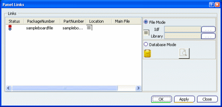
The Panel Links dialog box opens:

Select the appropriate line in the Links box.
To identify where you want to find the board and components, do one of the following:
-
Click Database Mode then
 to search for the board in the database.
 - Click File Mode, then browse using
the
Browse
 button to locate
the appropriate IDF file and, if needed, Library file.
Note: The library
file is optional.
-
Click Database Mode then
Click OK when done.
You return to the first dialog box.
Set options to import components.
You can Importing Boards from:
- The database
- A library file
- Both the database and a library file.
Optional: To import component data that takes the original MCAD or ECAD environment into account, select Associate a CSV file for placement and browse to select the CSV file of interest.
Important: This option is only valid if you import components from the database. For more information, see About CSV Files.
Optional: Set the hole import option.
Draw only is the default option.
For more information, see About Holes.
Tip: Selecting the right option can reduce processing time. Click OK to validate.
A progress bar lets you monitor the import operation.
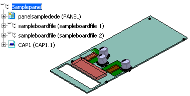
The result looks like this:
