About Holes | |||||
|
| ||||
Hole Import Options
Various options for managing holes are available in the Circuit Board Design dialog box when importing boards and panels.

- To display the contour in the geometry area but not drill holes, select Draw only. This is the default option.
- To drill holes, select Drill all.
- To customize how holes will be imported, select Custom
and:
- Select Drill only mounting (MNTG) and tooling (TLG) holes to drill mounting and tooling holes only, and display contours of other holes.
- Select Drill holes for diameter superior or equal to and enter a diameter in the box to drill holes whose diameter is more than or equal to the specified value.
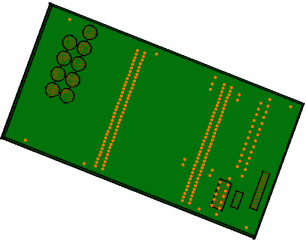
The following picture illustrates a typical import:

![]()
Hole Patterns
When you import an IDF file, hole coordinates are analyzed and the system tries to identify a pattern. If a pattern is recognized, it is re-created.
- If a rectangular pattern is recognized and you subsequently move or delete the component, the pattern is updated.
- If no rectangular pattern can be identified, then a user pattern is created but there is no link between the component and the pattern.
The system can only re-create hole patterns, not drill hole patterns.
Before importing, select the Keep link with selected object option (Tools > Options... > Infrastructure > 3D Shape Infrastructure).