Setting Displacement of Products and Parts | ||||||
|
| |||||
Set Displacement in SFC+
You can program a Set Displacement activity in SFC+.
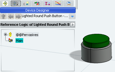
Open a resource that has sub-products (see a typical example below).
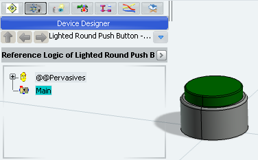
To open the SFC+ Editor, do one of the following:
- Expand the content of the Main block and double-click Behavior
 .
. - Right-click the Main block and select Behavior Editor.
- Select Behavior Editor
 in the Main window toolbar.
A 2D immersive window is opened to edit the block behavior. A toolbox at the right side of the window contains the SFC+ Editor commands.

Note: In our example, the block behavior is undefined, so the window is empty.
- Expand the content of the Main block and double-click Behavior
Select Set Displacement
 in the Activities toolbox.
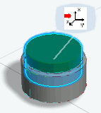
Select the part to move.
The selected part is highlighted and a bubble attached to it appears.
Tip: Select another part if you want to change the target. Click the bubble to confirm the part selection.
The Set Displacement Properties dialog box appears.
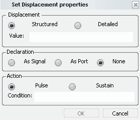
In the Displacement frame, you can define the displacement vector of the product.
- Structured: Value is a structured
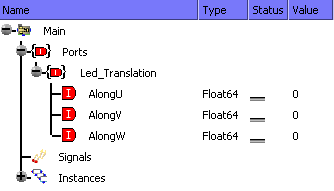
signal containing all the coordinates, that is, positions and angles about U, V and W. The signal type is:
{AlongU:float64;AlongV:float64;AlongW:float64;AboutU:float64;AboutV:float64;AboutW:float64} - Detailed: The coordinates can be set independently.
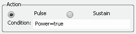
In the Action Data frame, you can define:
- The type of action: Pulse or Sustain
- A conditional expression applicable on the execution
of the action. If the condition is false, the action is not executed.
See a typical example below.
- Structured: Value is a structured
signal containing all the coordinates, that is, positions and angles about U, V and W. The signal type is:
Enter a port name for AboutW.
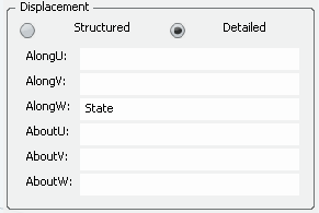
Note: You can enter any port or local signal name compliant with the Float64 type.
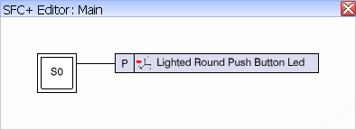
Click in the SFC+ Editor to position a new step.
A first step of the SFC+ graph is created. The action contains an icon identifying the activity Set Position followed by the name of the product (or the part) being the target of the activity.
Scroll over the action to see the parameters.
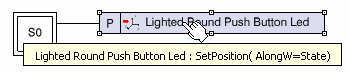
Tip: To modify the activity, double-click it. You can change the target of the activity and the parameters of the Set Displacement Properties dialog box. To test the behavior of the activity in simulation:
- Select the Main block in the Simulation Logic tree and click Play
 in the compass.
The block is compiled and the simulation is initialized. The Simulation toolbar and the Signals Monitoring window appear.
- Expand the Ports node of the Signals Monitoring window and force the value of State to 10. The part will move to 10 mm along the W axis.
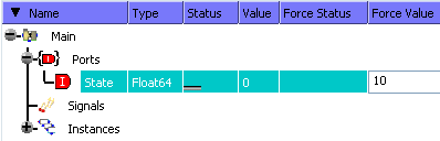
Note: Only the value of the signal emitted (AlongW in our example) is taken into account by the simulation. The other signals keep their current value.
- Click Next
 in the control bar of the compass. The device moves along the Z
axis.
in the control bar of the compass. The device moves along the Z
axis.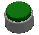
- Select the Main block in the Simulation Logic tree and click Play

![]()
Set Displacement in Dataflow
You can program a Set Displacement activity in Dataflow.
Open a resource that has sub-products. The Main block must be a Dataflow block (see a typical example below).
Note: To modify the kind of the block, select Block Definition in the block contextual menu and select SFC+ or Dataflow in the Kind drop-down box.
Double-click the Main block in the Simulation Logic tree.
A 2D immersive window is opened to edit the block behavior. A toolbox at the right side of the window contains the Block Editor commands.

Note: In our example, the behavior of the block is undefined, so the editor is empty.
Select the part to move.
The selected part is highlighted and a bubble attached to it appears.
Click the 2D editor to position the activity instance.
An instance of the activity Set Displacement is created.
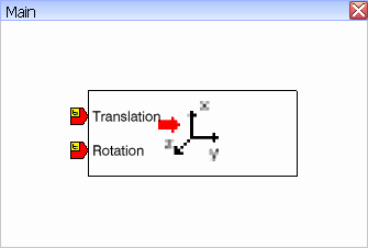
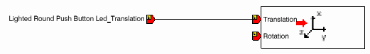
Two inputs ports are displayed:- Translation, type Translation {AlongU:float64;AlongV:float64;AlongW:float64}
- Rotation, type Rotation {AboutU:float64;AboutV:float64;AboutW:float64}
Note: The Translation and Rotation types are available as predefined types as soon as the activities Set Displacement or Get Position are used.
Select in the contextual menu of the port Translation.
To test the behavior of the activity in simulation:
- Select the Main block in the Simulation Logic tree and click Play in the compass.
The block is compiled and the simulation is initialized. The Simulation toolbar and the Signals Monitoring window appear.
- In the IO Monitoring window, expand the node Ports.
- Force the value of the Z port to 10 and press Enter.

- Click Next in the control bar of the compass. The part moves along the Z
axis.
Important: Only the value of the signal emitted (AlongW in our example) is taken into account by the simulation. The other signals keep their current value.
- Select the Main block in the Simulation Logic tree and click Play
