Getting Positions of Products and Parts | ||||||
|
| |||||
Get Position in SFC+
You can retrieve the postion of a part or a product with the Get Postion activity programmed in SFC+.
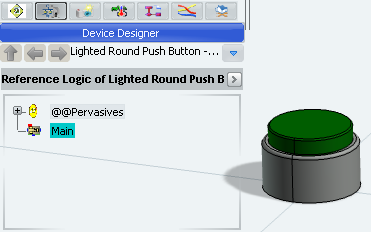
Open the sample created in the Set Displacement in SFC+ user task. The activity Set Displacement defined in the Simulation Logic of the resource allows the user to move the button cap while playing the simulation.
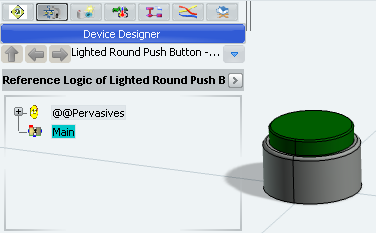
Select the Main block and double-click Behavior
 in the Main window.

- The SFC+ Editor appears as an immersive window at the center of the screen.
- A toolbox containing all the SFC+ Editor commands appears at the right side of the screen.
Select Get Position
 in the Activities toolbar.
Select the part being the target of the activity.
The selected part is highlighted and a bubble appears.
Tip: Select another part if you want to change the target. Click the bubble to confirm the part selection.
The Get Position Properties dialog box appears.
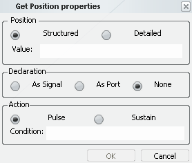
In the Displacement frame, you can enter the name of ports or local signals containing the target position.
- Structured: Value is a structured
signal containing all the coordinates, that is, positions and angles about X, Y and Z. The signal type is:
{AlongX:float64;AlongY:float64;AlongZ:float64;AboutX:float64;AboutY:float64;AboutZ:float64} - Detailed: The coordinates can be stored in different signals.
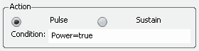
In the Action Data frame, you can define:
- The type of action: Pulse or Sustain
- A conditional expression applicable on the execution
of the action. If the condition is false, the action is not executed.
See a typical example below.
In the Declaration frame, you can define that the ports or signals used in the Position frame must be created with the activity. This must be done if the ports or signals are not already defined in the block.
- Structured: Value is a structured
signal containing all the coordinates, that is, positions and angles about X, Y and Z. The signal type is:
Enter a port name in the AlongZ box.
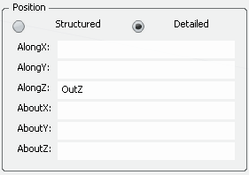
Note: You can enter any port or local signal compliant with the Float64 type.
Click OK and select the Step S0 in the SFC+ Editor window
A new action is added to step S0. The action contains an icon identifying the activity Get Position followed by the name of the product being the target of the activity.
Tip: To modify the activity, double-click the action. You can change the target of the activity and the parameters of the Get Position Properties dialog box. To test the behavior of the activity in simulation:
- Select the Main block in the Simulation Logic tree and click Play
 in the compass.
The block is compiled and the simulation is initialized. The Simulation toolbar and the Signals Monitoring window appear.
- Click Next
 in the control bar of the compass.
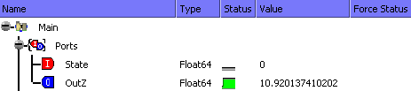
OutZ returns the Z position of the button cap. - Press Enter.
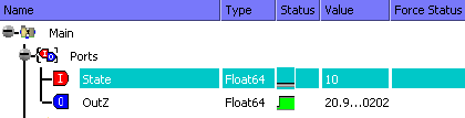
- Click Next in the control bar of the compass.
The device moves along the Z axis. Because of a one cycle delay, the value OutZ does not change.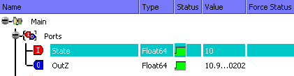
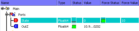
Warning: In SFC+, the position returned is not the position of the product/part at the current simulation step but the position at the previous simulation step. - Click Next again.
The value of OutZ is updated.
- Select the Main block in the Simulation Logic tree and click Play

![]()
Get Position in DataFlow
You can retrieve the postion of a part or a product with the Get Postion activity programmed in Dataflow.
Open the sample created in the Set Displacement in Dataflow user task. The activity Set Displacement defined in the resource allows the user to move the button cap while playing the simulation.
Double-click the Main block.

- The Block Editor appears as an immersive window at the center of the screen.
- A toolbox containing all the Block Editor commands appears at the right side of the screen.
Select the part being the target of the activity.
The selected part is highlighted and a bubble attached to it appears.
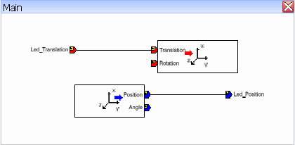
Tip: Select another part if you want to change the target. Click the place in the blank sheet where you want to position the activity block.
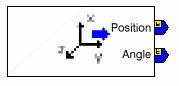
Two inputs ports are displayed:- Position, type Position {AlongX:float64;AlongY:float64;AlongZ:float64}
- Angle, type Angle {AboutX:float64;AboutY:float64;AboutZ:float64}
The types Position and Angle are available as predefined types as soon as the activities Set Displacement or Get Position are used.
If you want to change the name of the new port, double_click its icon.
The Block Properties dialog box appears. You can change the value of the field Name.
Note: In Dataflow, you cannot create more than one Get Position activity for the same target.
To test the behavior of the activity in simulation:
- Select the Main block thumbnail and click Play in the compass.
The block is compiled and the simulation is initialized. The Simulation toolbar and the Signals Monitoring window appear.
- Click Next.
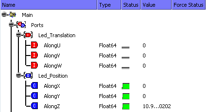
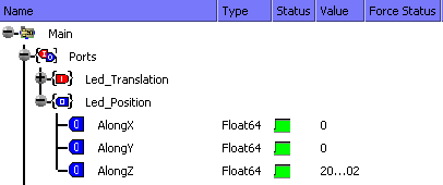
The Led_Position port returns the X,Y and Z position of the button cap.
- Force the value of AlongW to 10 and press Enter.
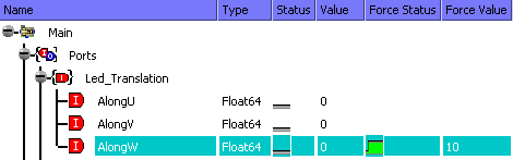
- Click Next.
The button cap moves to 10mm. The value of AlongZ is updated.
- Select the Main block thumbnail and click Play
