About Assembly Pattern | |||||
|
| ||||
The recommended structure to create an Assembly Pattern is the following:
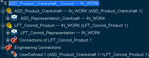
- A root product: ASD_Product_Crankshaft_Conrod.
- A 3D Shape containing the Geometrical Set of Axis Systems or the Part Design Pattern: ASD_Product_Crankshaft.
- A 3D Shape to be instantiated: LFT_Conrod_Product.
- An engineering connection in order to constrain the 3D Shape to be instantiated with an axis system or with the Part Design Pattern origin: UserDefined.1.
Once created, the assembly looks like this: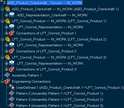
- Two instances of LFT_Conrod_Product have been added with a link to the set of engineering connections.
- An Assembly Pattern feature has been created: Assembly Pattern.1.
- Three Pattern engineering connections have been created to define positions of each LFT_Conrod_Product instances, including the original instance.
Important: The Pattern engineering connection can be edited and the Pattern constraint can be replaced by one or more other constraints.
- Any patterned product instances including the original instance, can be replaced by another product.
This recommended assembly structure allows you to instantiate the root product in another Assembly Pattern.