Using a Geometrical Set | |||
| |||
Click Assembly Pattern
 .
.
The Assembly Pattern dialog box appears.
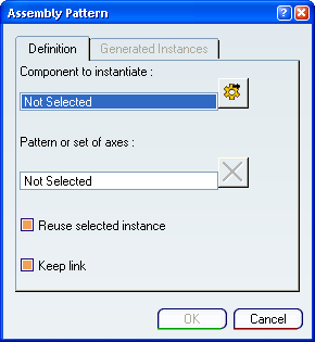
- Click
 opens the Object Selection dialog box in order to access component in database.
 - Reuse selected instance option allows you to reuse the selected component in the Assembly Pattern.
Important: Reuse the selected component means that this component will be kept at its current location if it is correctly constrained.
- Keep link option allows you to keep associativity between components and the Part Design pattern or geometrical set.
- Click
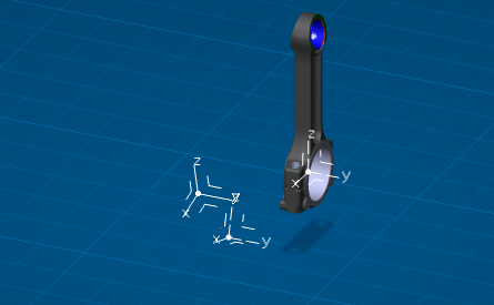
Select the component to instantiate.
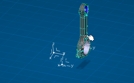
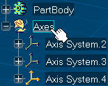
Select the geometrical set containing axis systems.
Click OK in the Assembly Pattern dialog box.
The Assembly Pattern is created.
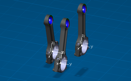
- Created pattern items, from the selected instance, appear in the specification tree.
- Assembly Pattern feature appears in the specification tree.
Click Update All
 .
.Double-click the representation containing the geometrical set in order to switch in Part Design workbench.
Note:
- You will go in the last activated representation workbench, if this one is not Part Design, select it from the Start
 button.
 - You can also double-click any feature in a representation in order to change to a representation workbench.
- You will go in the last activated representation workbench, if this one is not Part Design, select it from the Start
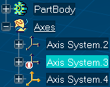
Right-click the Axis System.3 and select .
Axis System.3 is deactivated.
Important: We recommend to deactivate/activate Axis Systems instead of delete/add one. In this last case, pattern items and instance numbers are reordered.
Click Update All
.The Update Report dialog box appears.
Click Edit definition of the selected object
 .
.The Update Report dialog box disappears, and the Assembly Pattern dialog box appears: the Generated Instances tab is selected.
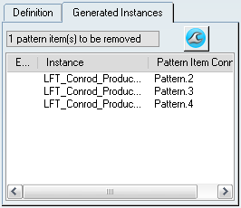
A message indicates that one pattern item has to be removed, the item corresponds to the deactivated axis system in the geometrical set.
Note:
- The message is customized according to the context: add item, remove item, etc.
- A contextual menu is available on each instance of the list to help to locate any instance: Center Graph and Reframe On.
Click Repair
 .
.The assembly pattern is updated.
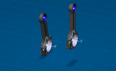
Useless pattern item has been removed from the specification tree and from the Generated Instances tab.
Click Update All
.