Creating a Shell Expansion View | ||||||
|
| |||||
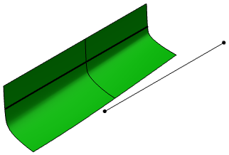
Open the structure system and draw a reference line in the X direction.
The reference line should be a straight line parallel to the center line of the ship.
Click Shell Expansion
 in the Operation toolbar.
The Shell Expansion dialog box appears.
The progress bar appears indicating the shell expansion view generation. A new node is added in the specification tree indicating the generated shell expansion drawing of the structure system. You can double-click the drawing node to view the shell expansion drawing.
Notes:
- Multi-selection of the shell panels is possible. However, the selected panels should lie only on any one side of the centerline i.e. starboard / portside.
- Expansion of the shell panels is possible only on any one side of centerline i.e. the starboard side or portside.
- Beams are excluded from the shell expansion drawing
- Stiffeners limited by shell panels are not generated in the shell expansion drawing, for example, deck transverse stiffener limited by the shell panels.
- You cannot update the shell expansion drawing. You need to create new drawing if any modifications are done.