Shell Expansion Dialog Box | ||||
|
| |||

Shell Expansion
- Shell Plates
- Select a shell plate in your 3D session, it appears in the Shell Plates box.
If you select more then one plate the icon
 is activated. Click the icon to check the list of the selected plate. You can replace or remove previously selected plates using this option and close the window.
 - Reference
- Select a straight line in your 3D session, it appears in the Reference box.
Only one reference element can be selected.
- Geometric Curve(s)
- Select a curve in your 3D session, it appears in the Geometric Curve(s) box.
The curve should have a shell like geometrical support for example intersection, projection, free boundary etc...
The expansion parameters are computed from this curve. It determines the position of the expanded plate.
If you select more then one curve the icon
is activated. Click the icon to check the list of the selected curves. You can replace or remove previously selected curves using this option and close the window. - Options...
- Click Options... to edit shell expasion options like GVS template, symmetry plane.
When you click Options..., the Shell Expansion Options dialog box appears.
![]()
Shell Expansion Options Dialog Box
The Shell Expansion Options dialog box contains the following options:
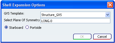
- GVS Template
- Select a GVS template in the GVS Template list. The selected template is used for generating shell Expansion drawing.
- Select Plane Of Symmetry
- Select a palne or a curve in your 3D session, it appears in the Select Plane Of Symmetry box.
- Portside / Startboard
- Select a Portside or Starboard option depending upon the selected shell plate.
While selecting the appropriate option, you should consider following points:
- For non symmetric hull, it might be required to generate a shell expansion for both side of the hull.
- If the hull surface is oriented along positive X direction, then:
- The starboard shell expansion represents structural objects (stiffeners, deck…) in the far side mode (hidden line mode).
- The portside shell expansion represents structural objects (stiffeners, deck…) in nearside mode (shown line mode).
- If the hull surface is oriented along negative X then it’s vice versa.