Creating a Functional Tolerancing and Annotation View

You can create a functional tolerancing and annotation (FTA) view using the Functional Tolerancing and Annotation workbench. These views are later used to generate 2D views in the Generative Drafting workbench, during 2D extraction of the 3D part and annotations.

This task shows you how to:


Before you begin: Open the structure to create FTA view.
Related Topics
About View Generation Modes
Creating a Logical View

Creating a Front View

You can create front, section, or section cut views/ annotation planes using the FTA workbench.

  1. Click Start > Mechanical > Functional Tolerancing and Annotation.

    The 3D Part / Product DS dialog box appears.

  2. Enter the necessary inputs and click Finish.

  3. Click Front View in the Views/Annotation Planes toolbar.

    The Tools Palette appears.

  4. Click Front View in the Tools Palette.

  5. Select a face.

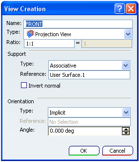
    The View Creation dialog box appears.

  6. Click OK.

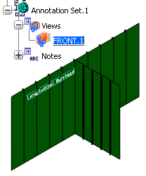
The section cut view is created. Front views are represented by a blue reference axis and are identified as Front View.1 in the specification tree.


Note: For more information about creating views and adding annotations, please refer to 3D Functional Tolerancing and Annotation User's Guide : View/Annotation Planes.

Creating a View from 3D

You can extract a 2D view from a 3D part with 3D annotations.

You need to apply the following settings:

  • Go to Tools > Options > Mechanical > Drafting > View tab. Make sure that Exact View is selected as the View generation mode.
  • Make sure that same standard is used in the .CATDrawing and .CATPart documents. In this example, ISO is used as the standard.

  1. Open the document where you have created the Front View.1.

  2. Click Start > Mechanical > Drafting.

    The Drawing / Representation DS dialog box appears.

  3. Enter the necessary inputs and click Finish.

  4. Click View From 3D in the Views toolbar.

  5. Select Front View.1 in the specification tree.

    A preview of the view is displayed in the drawing.

  6. Click in the drawing document to generate the view.

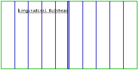
The images below show the view generated using Front View.1.