Creating a Bulkhead | |||
| |||
In the specification tree, select the 3D representation under which you want to create the bulkhead. Click Panel
 in the Authoring Object toolbar.
 The Plate dialog box appears.
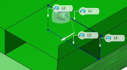
In the Support box, select cross planes as support for the transverse bulkhead.
You can do the selection in the design or specification tree or by using Reference Plane Browser.

Warning: It is important to select a support that is compatible with the selected category. For more information about selecting a support, refer to Molded Conventions. Select shell, deck plates and longitudinal bulkhead as the limiting object.
Limits are used to trim the excess plate by specifying a limiting object.
Selected objects appear in the Object column in the Limits box. The transverse bulkhead is trimmed along the selected limits in the preview mode. You can click Switch Side to toggle between the sides you want to limit.
To create the starboard side transverse bulkhead, click Switch Side. You can also click Remove to remove the limit.
To create multiple bulkheads, select another cross planes as support for the bulkhead in the Support box.
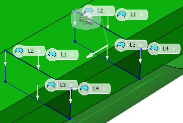
The transverse bulkheads are created.