More About Creating a Stiffener on Free Edge | |||||
|
| ||||
Support for Free Edge Stiffeners
This topic provides information about the support for free edge stiffeners.
A free edge stiffener can be created on an opening or several limits or on a curve.
There are two modes of selection of support for free edge stiffeners. The support can be based on either the opening feature, the limits of the panel.
Each mode is activated depending on the first selection.
Ex: If you select a panel limit, the creation mode will be limit.
You can select a limit or an opening interactively.
A free edge can be:
- The edges generated by openings
- The edges generated by limits
- Any other border edge.
Tips:
|
Notes:
- The limits are highlighted in blue, and the openings in yellow when you start free edge stiffener.
- Only the edges which are considered as free edges are highlighted with some dash lines.
- If a cursor is moved over on the free edge, it will be highlight in solid line the corresponding to the opening or the limit, and a tag displays the alias of the selected feature. Only the free edge limits are highlighted.
- The result corresponding to the selection of an opening or a list of limits must form a mono-domain result.
- The OK button is grayed out when the result is multi-domain.
- Limits with a multi-domain result (having multiple edges disconnected) are highlighted in red, and the tag will have a red icon to show the multi-domain.
- If the result of the opening is multi-domain, a preview of its edges are not displayed.
- If an opening is modified and becomes multi-domains then the free edge stiffener throws an update error.
- A separate stiffener on free edge object is created for every selected edge i.e. number of stiffeners on free edge are created for number of adjacent edges.
- The Extract command from Generative Shape Design workbench can be used for creating stiffener on free edge on the opening edge of the panel.
- Stiffeners on free edge can be created by selecting number of openings on the panel.
- While creating a stiffener on free edge, you can do mix selection i.e. you can select opening edges or free edges of panel simultaneously.
![]()
Trace Offset
This topic provides information about the trace offset for free edge stiffeners.
In the Offset box, specify the trace offset value.
If you want to set the trace offset for a stiffener on free edge, specify the offset value in the Offset box in the Geometry area.
Offset is set to the stiffener on free edge.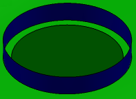
![]()
Limiting Free Edge Stiffeners
This topic provides information about the limits for free edge stiffeners.
By default, stiffeners are placed from end to end of the free edge you selected. If you need to resize a stiffener, you have to define the limits.
In the Stiffener on Free Edge dialog box:
In the Limit area, in the Name box, select Start box and select a starting limit. You can select a plane, plate, another stiffener or a surface. The stiffener is limited as soon as you make your selection.
Similarly define the End.
In the Offset box, you can define the offset value of each stiffener on free edge limit.
Note: Use Swap Ends to toggle between Start and End.
![]()
Web Angle
This topic provides information about the web angle for free edge stiffeners.
By default, the web of a stiffener is placed perpendicular to the plate. To change this angle, specify the required value in the Web Angle box.
If you want to place it at an angle then type the preferred angle value or use the arrows to change the value in the Web Angle box.
![]()
Defining Orientation
This topic provides information about the orientation of free edge stiffeners.
In the Stiffener on Free Edge dialog box, select the Material and Orientation tab.
To get the required orientation of stiffener, make the appropriate selection in the Plate side, Section orientation, Anchor point and Anchor point box.
You can orient the stiffener as explained below:
- Plate Side and Section Orientation
- Anchor Point and Anchor Point Offset
Plate Side and Section Orientation
You can Flip the Plate Side and Section Orientation to get the correct orientation. The images below show both operations.
Anchor Point and Anchor Point Offset
The anchor points that display in the Anchor Point box are defined in the molded convention resource set in Project Resource Management. Select one from the drop down list to get the correct orientation.
Anchor point offset allows you to modify the location of the anchor point of a face plate stiffener. As an example, a stiffener with a Center-Right Anchor point, and 0 mm Anchor point offset, is positioned equally to either side of the plate, as shown below. 
Changing the offset value moves the stiffener more to one side or the other. The images below show a stiffener that is not offset (left) and one that has been offset.
A stiffener with zero offset.
 |
A stiffener with offset.
 |
Note: In the image above thickness is shown for visualization purpose. You cannot see thickness in the Structure Functional Design workbench.