Placing a Part in Space | ||||
|
| |||
Place a Part on a Plane
You can place a part by selecting a plane.
Click Place Part
 in the Compass Toolbar.
A balloon opens.
Click Placement methods
 > Place in space
 > Define location by selecting a plane
 .
.The Part Subtypes dialog box opens to let you choose a part.
Select a plane.
The part is placed on the plane.
In the example below, a clamp has been placed.
![]()
Place a Part on Robot Base
You can place a part on robot base.
Click Place Part
in the Compass Toolbar.A balloon opens.
Click Placement methods
> Place in space > Define location on XY  .
.
The part is placed on the robot base.
![]()
Place a Part Using 3D Point
You can place a part on a point.
Click Place Part
in the Compass Toolbar.A balloon opens.
Click Placement methods
> Place in space .Click Use 3D point as location
 .
.The Part Subtypes dialog box opens to let you choose a part.
Select the point on which you want to place your part.
![]()
Place a Part Using Coordinates
You can place a part using coordinates.
Click Place Part
in the Compass Toolbar.A balloon opens.
Click Placement methods
> Place in space .Click Enter XYZ Coordinate
 in the balloon.
The Define Coordinates dialog box opens.
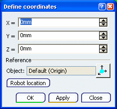
A red square appears as well to indicate the location where the part will be placed.
Enter a value for the X, Y and Z coordinates and click OK.
The red square has moved to the new location.
In the example below, the X value is 30mm, the Y value is 30mm and the Z value is 25mm.
The Part Subtypes dialog box opens to let you choose a part.
Click inside the Object field and select an object to make the coordinates relative to this object.
The red square has moved according to the XYZ coordinates and the object.
Note: In the previous tasks, it is possible to select a part to place before selecting a method placement.
The last selected part remains selected if you do not select another part.