Flexible Route Definition Dialog Box | ||||
|
| |||
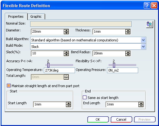
Properties
- Nominal Size
-
The size of the pipe/tube.
Note: This value is a string, and not necessarily the true size of the pipe. It points to the outside diameter value, which shows the true size. If you are filtering by nominal size, then you must enter the entire string as shown in the nominal size column.
- Route Size Table
This button opens the Flexible Pipe Reference Table which shows pipes available to you and some of their properties. You can make a selection in this table.
- Diameter
The outside diameter of the pipe/tube. If the Flexible Pipe Reference table is used, the value will come from the Outside Diameter column from the selected row.
- Thickness
Wall thickness of the pipe/tube. If the Flexible Pipe Reference table is used, the value will come from the Wall Thickness column from the selected row.
- Build Algorithm
- In the Build Algorithm box select Standard Algorithm or FLEX algorithm from the list.
- Standard Algorithm: If you use this option then the routing is based on mathematical calculations only. This means that the physical properties of the part you are using are not taken into account when routing.
- FLEX algorithm: The physical properties of the part you are using are taken into account when routing. Properties like material, gravity, pressure rating and operating temperature of the flexible are considered. You can set the direction in which the slack will sag by using a setting.
Note: FLEX algorithm option is only available if you have the Generative Piping and Tubing license. If you do not have the license then routing will use the Standard Algorithm.
- Build Mode
- In the Build Mode box select Slack, Bend or Length.
- Use Slack mode and enter a value in the Slack box to add additional length to the minimum length. If you use 0 slack between two defining points, the spline will be straight. If you define the flexible using two points, and the distance between the points is 40in, and you set the slack mode to 50%, the new length will be 60in.
- If you select the Bend mode, the bend radius will equal the value in the Bend Radius box and, additionally, the flexible will find the minimum distance between the points defining the route.
- Use Length mode when you know the fixed length of the flexible tube. You need to enter a value in the Total Length box.
- Slack
- If you select the Slack mode in the Build Mode box enter a value in the Slack box - to add additional length to the minimum length. If you use 0 slack between two defining points, the spline will be straight. If you define the flexible using two points, and the distance between the points is 40in, and you set the slack mode to 50%, the new length will be 60in.
- Bend Radius
- If you select the Bend mode in the Build Mode box, the bend radius will equal the value in the Bend Radius box and, additionally, the flexible will find the minimum distance between the points defining the route.
- Accuracy
- Moving the slider to the right increases accuracy. Greater accuracy will give you a smoother flexible. It will also degrade performance.
- Flexibility
- If the material on the flexible you are using is not defined, then you can use this slider to set flexibility. Moving the slider to the right increases flexibility.
- Operating Temperature
- Enter the operating temperature in the Operating Temperature box.
- Operating Pressure
- Enter the operating pressure in the Operating Pressure box.
- Total Length
- Use Length mode in the Build Mode box when you know the fixed length of the flexible tube. You need to enter a value in the Total Length box.
- Maintain straight length at end from part port
- Select this option to specify the straight length to be maintained at the start and the end of the flexible pipe. Once you select this option then the Start and End options are activated.
Note: If you select the Maintain straight length at end from part port option, then two new points are created at a distance specified in the Start Length and End Length boxes. You can delete these points by unselecting the Maintain straight length at end from part port option. Also, during further processing to manipulate these points, you need to use the Edit Properties dialog box.
Important: - Any change in the slack value has no effect on the straight portion of the flexible route.
- This option is independent of the Maintain Straight route from port option in the Tools > Options > Equipment > Fluid Discipline > Fluid Systems Detail Design > Piping and Tubing tab, which is applicable for rigid route only.
- Start
- Specify the straight length to be maintained at the start of the flexible pipe in the Start Length box.
- End
- Specify the straight length to be maintained at the end of the flexible pipe in the End Length box.
You can select the Same as start length check box to maintain equal straight length at the start and the end of the pipe. If you select the Same as start length check box, then the End Length box becomes unavailable.
![]()
Graphic
The Graphic contains the following options:
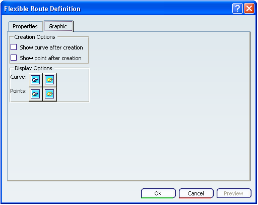
- Creation Options
- Show curve after creation
Select this option to display the curve, or centerline, of the pipe after routing.
- Show point after creation
Select this option to display the points, or nodes, of the pipe after routing.
- Display Options
Use the Show/Hide buttons to display or hide curve or point in a route.