You can create assigned product flow animation to visualize and understand the behavior of systems
and products in the model. When an assigned product is selected on any
system tile, Source system is the start point of the animation.
Select an assigned product on the Source system tile.
Click Play  in PLM Compass.
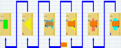
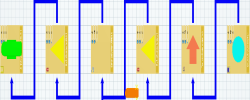
The selected product moves from one system tile to another based on the flow connection starting from the origin Source system.
Make sure that product representation is GREEN on the Sink system.
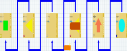
Select a Buffer system and remove product assignment using Define Operations dialog box.
Select a product on the Source system tile and click Play  in PLM Compass.
Product
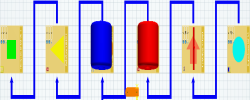
representation is ORANGE in color when it passes over the Buffer system, and ends at Sink system as
GREEN.
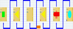
Select a Transfer system and remove product assignment using Define Operations dialog box.
Select a product on Source system tile and click Play  in PLM Compass.
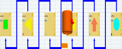
Product
representation is RED in color when it passes over the Transfer system, and ends at Transfer system only.
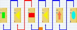
Double-click product flow link between the General and Transfer system.
- Click Detail Selected Material Flow Link
 in the balloon toolbar.
- Remove product flow for the connection.
Select a product on Source system tile and
and click Play  in PLM Compass.
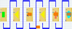
Product
representation stops at General system and both product
representation and
connection are RED in color.
![]()


 in the balloon toolbar.
