Open a Product and save it in the database.
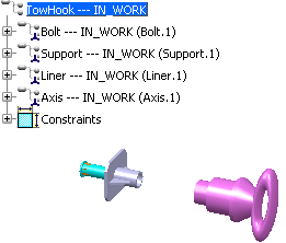
Select PLM Access > New.
Expand the All types node and select
Knowledge Template. Click Next.
Enter the name of the template (TowHook in this
example) and click Finish.
In the Components tab, click Add
reference... The Select a reference to insert in the
template dialog box is displayed.
Note:
The Action to perform after duplication option enables you, for each root of the template, to select the Instantiate in a Product or the Open option.
Enter the name of the Product and click Search
to search for the Product you saved in the database.
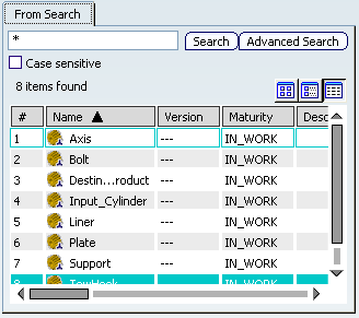
Select it in the list and click OK.
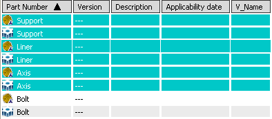
In the Components to keep section, click
all components except the Bolt and click
 .
.
Click the Inputs tab. In our example,
we expand the Support node. The inputs are displayed.
Click Add. The Select inputs
dialog box is displayed. Select Surface.1, Curve.1,
and Surface.2.
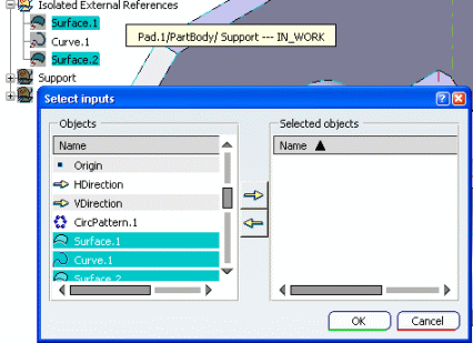
Assign them a role in the Name field:
Curve.1
 CurveOnExteriorSurface
Surface.2; Surface.2
  ExteriorSurface; Surface.2
 CylindricalSurface.
Click the Parameters tab to add parameters,
expand the Support node and click Add... in the
Parameters in representations section. The Select parameters
window opens.
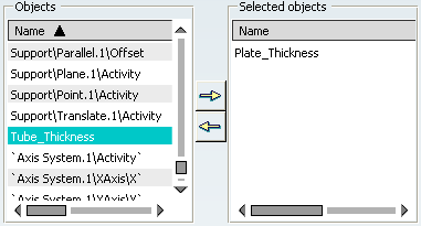
Select Tube_Thickness and Plate_Thickness
and click the right arrow to move them to the Selected objects
column.
Click the TowHook node and click Add
in the Components attributes section.
In the Name field, enter TowHook part
number.
Click the Support node and click
Add in the Components attributes section.
In the Name field, enter Support part
number.
Click the Liner node and click Add in
the Components attributes section.
In the Name field, enter Liner part number.
Click the Axis node and click Add in
the Components attributes section.
In the Name field, enter Axis part number.
The Part numbers are added to the tree.
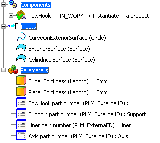
The PLM Template is created.
Save your template and close it.