Click Translate
 if you are working in Part Design or click Translate
 if you are working in Generative Sheetmetal Design.
The application issues a question about the
result you wish to obtain:
- you can decide to keep the new specifications induced
by the operation: in this case, just click Yes
to go on using the command you have just selected.
OR
- you can decide not to keep the new specifications: in
this case, click No to cancel the command
you have just launched.
Click Yes.
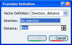
The Translate Definition dialog box appears.


Keep Direction, Distance
to define the translation vector.
The distance is a scalar value that
is moved along the directional vector. This vector may be supplied
as a line or plane. If a plane is provided, the normal to the
plane is used as the directional vector. Select
zx plane.
Specify the translation distance by entering a value
or using the Drag manipulator. For example, enter 100mm.
Click OK to create the translated element.
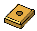
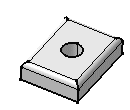
The element (identified as Translat.xxx) is added
to the specification tree.
