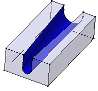
Click Removed Multi-sections Solid
 .
.
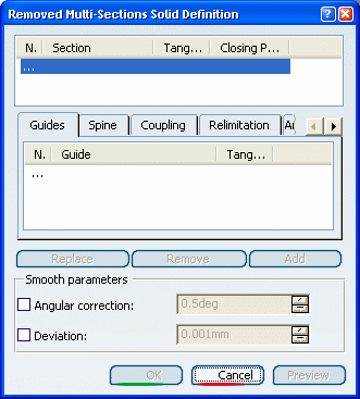
The Removed Multi-sections Solid Definition
dialog box appears.
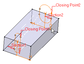
Select both section curves as shown Sketch.3
and Sketch.4:
They are highlighted in the geometry area.
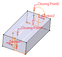
Select Closing Point 2 as shown on Section
2 to redefine the closing point.
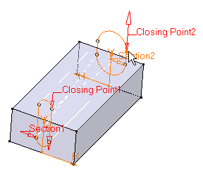
Click Closing Point 2 arrow to reverse the
direction.
It is possible to edit the feature reference elements
by first selecting a curve in the dialog box list then choosing a button
to either:
- Remove the selected curve
- Replace the selected curve by another curve.
- Add another curve.
Click OK to create the removed
multi-sections solid.
The feature (identified as Multi-sections
Solid.xxx) is added to the specification tree.
