Displaying and Editing Representation Properties | |||||
|
| ||||
Select the representation of interest in the specification tree.
Select Edit > Properties or select the Properties contextual command.
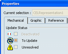
The Properties dialog box appears, containing four tabs dealing with the 3D representation:
- Mechanical
- Graphic
- Reference
- Colors
The Mechanical tab displays information related to the building of the representation.
Click the Graphic tab.
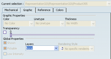
Fill in the fields with your own information.

Choose one of the different types of Default Graphic Properties. Select the V6 and V5 Themes if you wish to use V6 or V5 colors for Wire, Surface, Volume and Solid features on new 3D Shape. Select Settings Theme if you wish to retrieve default properties defined in the Tools>Options dialog box.
The Custom theme is automatically selected when you change a color or an opacity below.
 By
default, V6 Theme is selected.
By
default, V6 Theme is selected.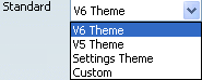
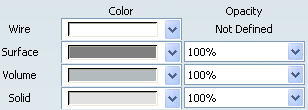
Click on the different properties to change the Wire, Surface, Volume or Solid colors and opacity.
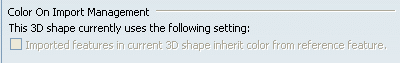
If your administrator selected Color on import management property is editable in the Tools > Options dialog box, the Imported features in current 3D shape inherit color from reference feature option is then available.
Select it if you want an automatic export of colors.
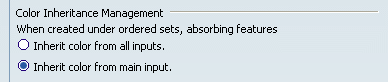
Select Inherit color from all inputs: whenever you create a Generative Shape Design absorbing feature (Trim, Split features, etc.), the color assigned to this feature is the color of the element you have selected first to create it (main input) when the absorbing feature is created under the same Ordered Set (Hybrid Body or OGS) as its main input.
Conversely, if you keep Inherit color from main input, the color assigned to absorbing features is defined using the colors of the main inputs you have selected. This behavior is therefore the same as the one that applies to Part Design features.