Creating Variable Radius Fillets | |||||
|
| ||||
Click Variable Radius Fillet
 .
. The Variable Radius Fillet Definition dialog box appears.
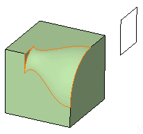
Select the open edge to be filleted.
You can define variable radius fillets on closed edges. For more information, see Variable Radius Fillets Using Closed Edges. The application detects both vertices and displays two identical radius values. The
 icon available after the Edges to fillet box lets
you edit the list of the faces to be filleted. For more information
about that capability, see
Editing a List of Elements.
Optionally, click Preview to see the fillet to be
created.
icon available after the Edges to fillet box lets
you edit the list of the faces to be filleted. For more information
about that capability, see
Editing a List of Elements.
Optionally, click Preview to see the fillet to be
created.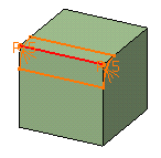
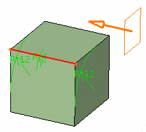
Enter a new radius value to simultaneously change the radius of both vertices. For example, enter 12mm.
The new radius value is displayed on both vertices. The preview is modified accordingly. You can use the radius value R=0 to create a variable radius fillet.
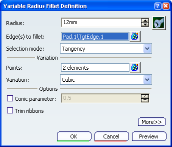
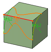
Enter a new radius value for this point: enter 4. The new radius value is displayed.
This is your preview:
Click OK to confirm the operation.
The edge is filleted. The specification tree indicates this creation.
To access additional options, expand the dialog box by clicking More..
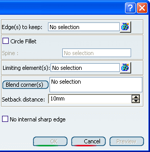
Click the Limiting elements box and select Plane.1 as the plane that will trim the fillet.
An arrow appears on the plane pointing to the portion of material that will be kept.
Click OK.
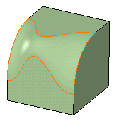
The variable radius fillet is trimmed to Plane.1. The final part looks like this: