Creating Drafts from Reflect Lines | |||||
|
| ||||
Click Draft Reflect Line
 .
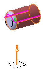
The Draft Reflect Line Definition
dialog box is displayed and an arrow appears, indicating the default
pulling direction.
.
The Draft Reflect Line Definition
dialog box is displayed and an arrow appears, indicating the default
pulling direction.Contextual commands creating the pulling directions you need are available from the Selection box:
- Create Line: For more information, see Generative Shape Design User's Guide: Creating Wireframe Geometry: Creating Lines..
- Create Plane: see Generative Shape Design User's Guide: Creating Wireframe Geometry: Creating Planes..
- X Axis: the X axis of the current coordinate system origin (0,0,0) becomes the direction.
- Y Axis: the Y axis of the current coordinate system origin (0,0,0) becomes the direction.
- Z Axis: the Z axis of the current coordinate system origin (0,0,0) becomes the direction.
If you create any of these elements, the application then displays the corresponding icon next to the Selection box. Clicking this icon enables you to edit the element.
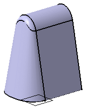
Select the cylinder. The application detects one reflect line and displays it in pink . This line is used to support the drafted faces.
The
 icon
available after the Faces to draft box lets you edit the list
of the faces to be drafted. For more information about that capability,
see Editing a List of Elements.
icon
available after the Faces to draft box lets you edit the list
of the faces to be drafted. For more information about that capability,
see Editing a List of Elements.Click Preview to get an idea of what the draft will look like.
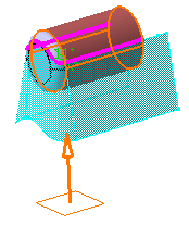
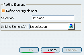
Select Define parting element and select plane zx as the parting element .
Contextual commands creating the parting elements you need are available from the Selection box:
- Create Plane: for more information, see Generative Shape Design User's Guide: Creating Wireframe Geometry: Creating Planes.
- XY Plane: the XY plane of the current coordinate system origin (0,0,0) becomes the parting element.
- YZ Plane: the YZ plane of the current coordinate system origin (0,0,0) becomes the parting element.
- ZX Plane: the ZX plane of the current coordinate system origin (0,0,0) becomes the parting element.
- Create Join: joins surfaces or curves. See Generative Shape Design User's Guide: Performing Operations on Shape Geometry: Joining Surfaces or Curves..
- Create Extrapol: extrapolates surface boundaries or curves. See Extrapolating Surfaces and Extrapolating Curves.
If you create any of these elements, the application then displays the corresponding icon next to the Selection box. Clicking this icon enables you to edit the element.
Click OK to create the draft feature.