Reorder One Feature using the After Option
You can reorder a feature using the After option. The feature will be positioned after the selected feature.
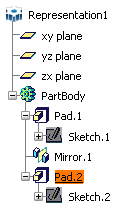
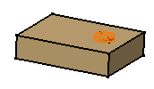
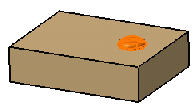
Your initial data consists of a pad that was mirrored
and a second pad created afterwards. As the order of creation is wrong,
you are going to reorder the second pad so as to mirror the whole PartBody.
Position your cursor on Pad.2. and select Edit > Pad.2 object
> Reorder...
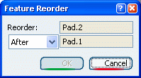
The Feature Reorder dialog box
appears. The default reorder option is After. For the purpose
of this scenario, keep this option. Select Pad.1 to specify the new location
of the feature.
This name appears in the After box.
Click OK.
The part rebuilds itself completely or partially, depending on the chosen
option for
Update operations.
When the update is complete, to see the resulting geometry,
use Define in Work Object to set Mirror.1 as the current
feature.
The mirror feature appears after the creation
of the second pad, which explains why this second pad is now
mirrored.


Reorder Several Features at a
Time
You can reorder two or more features at a time by multi-selecting the features and reordering them.
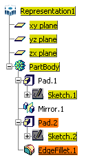
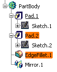
Multi-select Pad.2. and EdgeFillet.1
then select Edit > Selected objects > Reorder....
Our selection includes two features consecutively positioned under the
same tree node.
Non-Consecutive Features
If the features are not strictly consecutively positioned
under the same tree node, you can reorder them provided they are independent:
with no parents (except for XY, YZ or ZX planes or axis systems located
just below the part in the tree) and with nor children.
Otherwise, the operation is not possible and an error
message is issued.
In our scenario, the application detects non-available
locations and display them in yellow.
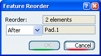
The Feature Reorder dialog box
appears. Select Pad.1 to indicate the new location for
Pad.2 and EdgeFillet.1.
The dialog box shows that two elements are to be reordered after
Pad.1.
Click OK to confirm.
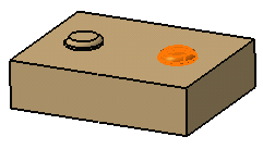
The 3D shape rebuilds itself. Both Pad.2 and EdgeFillet.1
are now mirrored. To see the resulting geometry as shown below, set
PartBody as the current object using Define in Work
Object.
|


