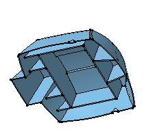
Select Part Body.
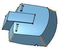
In our example, the part body to be copied looks like this:
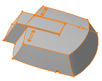
Select Edit > Copy to copy the part body.
Open a new representation and position the cursor anywhere
in the specification tree.
Select Edit
> Paste Special... .
The Paste Special dialog
box appears. Three paste options are available:
- As specified in Part document:
the object is copied as well as its design specifications
- As Result With Link: the object is copied
without its design specifications and the link is maintained
between the reference and the copy.
- As Result: the object is copied without its
design specifications and there is no link between the reference
and the copy.
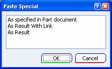
For our scenario, select As Result With Link,
and click OK. A new Body node including the copied
geometry is created in the new target representation. You will notice
that the specification tree displays it under the name of Solid.1 .

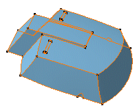
Now, if you wish, you can fillet four edges. You can
actually perform any modifications you need.
Return into the first representation.
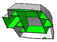
Use Remove to remove material from the part
body.
Note:
In the target document, the graphic symbol used for Solid.1 in the tree turned red. This means that the initial Part Body underwent transformations and the relation between the Part Body and the import is not synchronized. The red symbol only reflects the relation status, not the link status. To see the link status use Edit > Links and Relations....
What you need to do is synchronize the copied object
with its reference. Select Edit > Links and Relations...
The Edit > Links and Relations.... dialog box is displayed.
Click Synchronize link
 .
This operation changes the status of the imported geometry as you can
see in the Status column of the dialog box.
Click OK to close the dialog box.
The relation between the Part Body and the import is now synchronized.
However the geometry needs updating even if your session is in automatic
update mode.

Click
 .
The solid now reflects the change: material is removed. The specification
tree indicates that the part body has integrated the modifications made
to the original part body.

