More about Drafts with Parting Elements | ||||
|
| |||
Parting Element
This section provides information on the options used to define a parting element.
To define the parting element, you can select:
- Parting = Neutral to reuse the plane you selected as the neutral element,
or
- Define parting element and then explicitly select a plane or a planar face as the parting element.
| Important: The Draft both sides check box is applicable only to the faces which are cut by the parting element. The selected faces which are neither present on the pulling direction side nor cut by the parting element are not considered for drafting. |
When using a parting element and a limiting element, both selected elements must intersect to produce a draft feature.
Contextual commands creating the parting elements you need are
available from the Selection box:
- Create Plane: see Generative Shape Design User's Guide: Creating Wireframe Geometry: Creating Planes..
- XY Plane: the XY plane of the current coordinate system origin (0,0,0) becomes the parting element.
- YZ Plane: the YZ plane of the current coordinate system origin (0,0,0) becomes the parting element.
- ZX Plane: the ZX plane of the current coordinate system origin (0,0,0) becomes the parting element.
- Create Join: joins surfaces or curves. See Generative Shape Design User's Guide: Performing Operations on Shape Geometry: Joining Surfaces or Curves..
- Create Extrapol: extrapolates surface boundaries or curves. See Generative Shape Design User's Guide: Performing Operations on Shape Geometry: Extrapolating Surfaces and Extrapolating Curves.
If you create any of these elements, the application then displays the corresponding icon next to the Selection box. Clicking this icon enables you to edit the element.
![]()
Draft Form
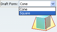
Draft Form provides two types of draft computation modes: Square and Cone.
Both computation modes
provide the same geometrical result if the neutral line is included
in a plane normal to the draft plane. For all other geometrical
contexts, you will have to decide to use one of these options. The
choice of the option to set will be done empirically.
- Square: mathematically speaking, the result obtained is
never exact but most of the time lets you create a satisfactory
draft feature.
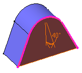
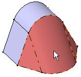
Here is an example of a draft feature obtained using Square:


Important: We recommend not to use Square when the surface you want to draft is very long. - Cone: the application uses envelops of cones defined
along a given curve to generate draft features.
When the use of Square does not guarantee that parts will be easily removed from their molds, Cone is the alternative option to be set. Mathematically speaking, the result obtained is always exact but sometimes produces twisted surfaces.