More about Basic Drafts | ||||
|
| |||
Draft Definition Dialog Box
This section describes the various options available in the Draft Definition dialog box to create a basic draft.
Draft Type
The Constant Angle Draft option
![]() is activated. Clicking the icon to the right
is activated. Clicking the icon to the right
![]() displays the options for creating variable angle drafts.
displays the options for creating variable angle drafts.
Faces to Draft
There are two ways of specifying the face to be drafted: either explicitly by selecting the face of interest, the face then appears in the Faces to Draft area), or by checking Selection by neutral face as explained below.
When using the explicit selection mode, the selected objects are displayed in dark pink.
Selection by Neutral Face
Selection by neutral face detects the face to be drafted once the neutral element has been selected.
Neutral Element
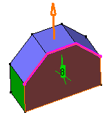
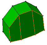
- It is possible to select several faces to define the neutral
element. By default, the pulling direction is given by the first
face you select. This is an example of what you can get:
Draft Definition
 Result
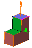
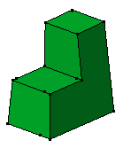
- We recommend you use a neutral element intersecting the faces to be
drafted. However, in some cases, you can use neutral elements that do not
intersect the faces. This is possible if the neutral element is
made of only one face. This is an example of what you can get:
Draft Definition
 Result
- If the neutral element does not belong to the body which faces you want to draft, it then needs to be large enough to fully intersect those faces.
Propagation
The Propagation option can be set to:
- None: there is no propagation.
- Smooth: the application integrates the faces propagated in tangency onto the neutral face to define the neutral element.
Pulling Direction
Contextual commands creating the pulling directions you need are available from the Selection box:
- Insert Wireframe > Create Line: For more information, see Generative Shape Design User's Guide: Creating Wireframe Geometry: Creating Lines.
- Insert Wireframe > X Axis: the X axis of the current coordinate system origin (0,0,0) becomes the direction.
- Insert Wireframe > Y Axis: the Y axis of the current coordinate system origin (0,0,0) becomes the direction.
- Insert Wireframe > Z Axis: the Z axis of the current coordinate system origin (0,0,0) becomes the direction.
- Insert Wireframe > Create Plane: see Generative Shape Design User's Guide: Creating Wireframe Geometry: Creating Planes.
Parting Element
To know how to use Parting Element, see Creating Drafts with Parting Elements in the Part Design User's Guide.
Limiting Elements
While drafting a face, you can limit it by selecting one or more faces or planes that intersect it completely.
When using several limiting elements, make sure that they do not intersect on the face to be drafted.
Contextual commands creating the limiting elements you need are available from the Limiting Elements box:
- Insert Wireframe > Create Plane: for more information, see Generative Shape Design User's Guide: Creating Wireframe Geometry: Creating Planes..
- Insert Wireframe > XY Plane: the XY plane of the current coordinate system origin (0,0,0) becomes the limiting element.
- Insert Wireframe > YZ Plane: the YZ plane of the current coordinate system origin (0,0,0) becomes the limiting element.
- Insert Wireframe > ZX Plane: the ZX plane of the current coordinate system origin (0,0,0) becomes the limiting element.
- Insert Operations > Create Join: joins surfaces or curves. See Generative Shape Design User's Guide: Performing Operations on Shape Geometry: Joining Surfaces or Curves..
- Insert Operations > Create Extrapol: extrapolates surface boundaries or curves. See Generative Shape Design User's Guide: Performing Operations on Shape Geometry: Extrapolating Surfaces and Extrapolating Curves..