Checking the Tool Length for Collisions

You can check a tool path to identify all the points where the tool collides with the part.

  • If you consider the tool alone, only the cutting length of the tool is taken into account.
  • If you consider the tool with its tool holder, the tool gage and the cutting length are taken into account.
  • Using tool assembly user representations greatly improves the collision checking between the tool and tool holder and the part.

Related Topics
About the User Representation for the Tool
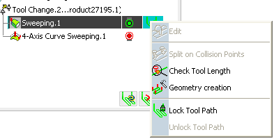
  1. In the Activities Process Tree, select the tool path and place the cursor in the Computed column.

    1. Right-click the tool path to display the contextual menu providing tool path edition commands.

    2. Select Check Tool Length .

      A dialog box is displayed.

  2. Click Extra geometry to add additional geometry to the part in the Machining Operation where the tool path was computed.

    Additional geometry may be a face or a clamp that you would rather avoid using in the computation and that is not defined in the Machining Operation.

  3. Set the other parameters:

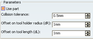
    • When you select Use part, the part you defined in the Machining Operation is used to compute the collision points.
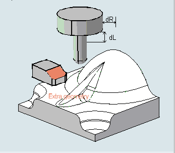
    • Collision tolerance defines the distance within which the tool holder is considered to be in collision.
    • Offset on tool holder radius and Offset on tool length define the tolerance distances specific to the tool holder radius and tool length.

  4. Click Apply.


    • The tool path is displayed on the part. The points where the tool holder is in collision with the part are shown in red.

    • A small dialog box is displayed that gives the number of collision points on this tool path, the minimum tool length that is required in order to avoid having collision points and the coordinates of the current point (move the mouse over the tool path to see the coordinates change for each point) plus reference data on the tool length and the offset on the tool length. You can also display the tool on the tool path.

  5. Click Cancel to close the dialog box.


    • This is only a visual check to let you see where the collision points are and find the tool length that is required to avoid them.
    • If a tool holder is defined, the dialog box displays information on the tool gage.
    • You now have the choice of either changing the tool length or editing the tool path in order to get rid of the collision points. If you want to change the tool length you must create a new tool or select another tool.

  6. Select the tool path again in the Activities Process Tree. Choose Area modification in the contextual menu.

    The tool path is displayed.

  7. Click Select collision points .

    The same dialog box as above is displayed.

  8. Change the parameter values if you wish.

  9. Click Apply to display the collision points in red on the tool path.

  10. Cut () the collision points from the tool path.