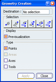
Geometry Creation Parameters | ||||
|
| |||

- Destination
- Defines the PartBody of the geometrical set where the geometry will be created.
- Selection
Offers icons corresponding to different selection options:

- Selects the first point of the tool path.

- Selects the last point of the tool path.

- Selects all the points between the first point of the tool path and the point picked.

- Selects all the points between the point picked and the last point of the tool path.

- Selects all the points between two points picked.

- Selects all the points of the tool path.
Note: You can also pick one point on the tool path.
- Display
 By default,
the Previsualization option is activated,
i.e. the element of the type selected below is visualized. You can
deselect this option. However, the points of the tool path are
always visualized.
 Note: If you want to only visualize the geometry, do not click Apply since it would create the elements of the type selected.
- Type
- Lets you select the type of elements you want to visualize or to
create.
- Points: creates points.
- Areas:
- available if the type Points is selected, and if several points of the tool path are selected.
- creates a join of lines from the portions of path selected.
- Axes: creates tool axes (as points and lines).
- Tools: creates tools (as revolves).
- Apply
- becomes available once you have selected a Destination
- creates the elements of the type you
have selected:
- select an area and a type of elements to create,
- click Apply,
- repeat these steps to create elements on several areas.
- Close
- Exits the command.
Note: The elements created by Apply are not erased.