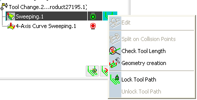
In the Activities Process Tree, select the tool path and place the cursor in the Computed column. - Right-click the tool path to display the
contextual menu providing tool path edition commands.

- Select Geometry creation


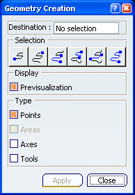
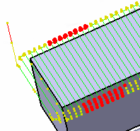
The tool path and the dialog box are displayed:

 By default,
Previsualization is selected: the previsualization of points is requested.
Place the cursor on Destination and select a destination body. Select an area of the tool path: - Click one of the Selection icon.

- Pick the first and the last points of the selection.

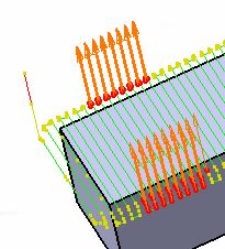
Set Type to Axes. Axes are
displayed on the tool path.

Click Apply.
The axes are created under the
Geometrical set corresponding to the Machining Operation. Click Close to exit the action.
|