Creating Attachment Ports | ||||||
|
| |||||
Deactivate the Resource Selection
 filter.
Click Create Attachment Port
 in the Attachment toolbar.
Click Create Attachment Port
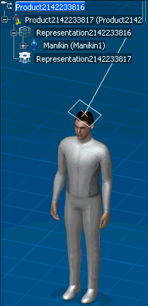
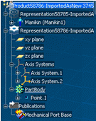
in the Attachment toolbar.Select the Device in the 3D viewer or in the tree.
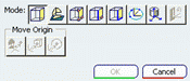
- If the Device has only one 3D shape, but has no Axis system defined on it, the Plane Selection dialog box appears letting you define the Origin and Orientation of the Axis system
- If the Device has only one 3D shape, and has an Axis system defined on it, then a message box appears asking you whether you want to create another Axis system.
- If you click Yes, the Plane Selection dialog box appears to help you define the new Axis system.
- If you click No and only one Axis system is defined, the Port Definition dialog box appears with that Axis system preselected.
- If you click No and multiple Axis systems are defined, you are prompted to select from the existing Axis systems in the viewer.
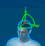
- If the Device has only one 3D shape, but has no Axis system defined on it, the Plane Selection dialog box appears letting you define the Origin and Orientation of the Axis system
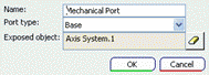
In the Port Definition dialog box that appears:
- Check that the Exposed object is set to the previously selected axis system.
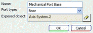
- Click OK to create the attachment port.
- Check that the Exposed object is set to the previously selected axis system.