Tool Assembly Conventions for Turning | |||||
|
| ||||
General Considerations
The Machining Axis is always a direct axis system. For example, ZX defines a direct axis system with Z as the spindle axis and X as the radial axis.
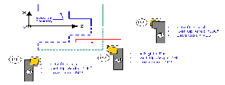
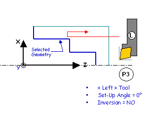
Selected geometry (for example, Finish Profile Turning) can be selected either in X+ or X- :
- the system figures out whether machining is in X+ or X- based on insert-holder orientation (as defined using set-up angle)
- depending on the options of the machining operation, several possibilities might exist (for example, Frontal machining). User option is then available (X+/X-) to specify what the system should do.
The output point definition is considered according to the X+/Z+ quadrant.
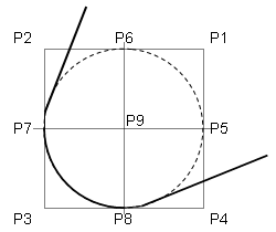
Examples below deal with horizontal lathe machine tool.
![]()
Insert Holder
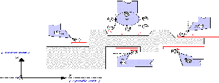
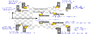
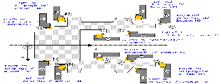
Different settings of the setup angle, invert tool, and hand style parameters result in different configurations for positioning the tool .
Left Tool: Insert is visible and points to left:
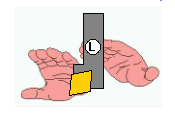
Inverted Left Tool :

Right Tool: Insert is visible and points to right:
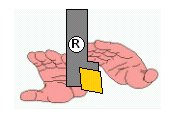
Inverted Right Tool:

![]()
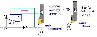
Spindle Rotary Direction
With a horizontal lathe machine tool the convention for spindle rotary direction defined in the Generic Machine dialog box is as follows: Looking into Z direction, Chuck and Jaws at your back.
Clockwise:
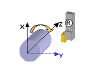
Counterclockwise:
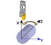
The following represent common settings:
![]()
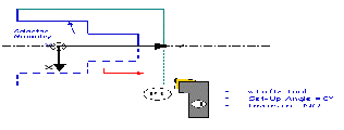
180 degree Setup Angle
When setup angle is set to 180 degree, machining takes places in X- as system detects that this is what the tool can machine (geometry can be selected in X+ or X-).
