Assembling Components to Build a Machine | ||
| ||
Assemble Product
You can build a NC resource using components that have already been created, that is, assemble existing parts within the product structure. This is done in the Assembly Design workbench.
Click
 , to enter the Assembly Design workbench.
Right-click Product node, and select
The Select products to insert dialog box appears.
![]()
Position the Inserted Parts
You can position the components correctly.
Right-click compass and select Snap Automatically to Selected Object.
Select the Part in the resource tree.
The compass snaps to this component in the graphics area.
![]()
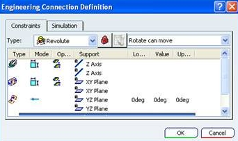
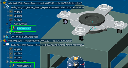
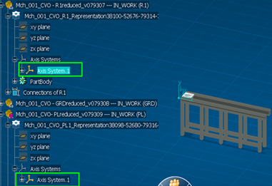
Create Engineering Connections
You can create Engineering Connections after inserting the products. You must create Engineering Connections to fix these products to the NC resource, using the Assembly Design workbench. The supported engineering connections are Revolute, Prismatic, and Rigid. The Fixed Engineering Connection must be defined along with other engineering connections. It is mandatory to create a Fixed Engineering Connection. Fixed part is the one which does not move. When modeling controlled machines, it is recommended to use the CATIA Axis Systems to define the joints that comprises the controlled degrees of freedom. This allows for a repeatable and consistent definition of joint zero position and joint motion positive direction. These best practices should be applied for all those engineering connections created through FBDI whose directions do not match with corresponding V5 joint directions.
For Rotational Joint
- Set the Mode to be Controlled
 By default,
its value is 0 degree.
By default,
its value is 0 degree.
- Set the Mode to be Controlled
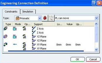
For Translational Joint
- Set the Mode to be Controlled, and mode to Same.
By default,
its value is 0 degree.
An offset can also be added along with the lower and/or upper limit.
- Set the Mode to be Controlled, and mode to Same.
![]()
Create a Mechanism
You can create Mechanism in NC resource.
Select the root node of the product tree, then click Create a New Mechanism
 in the Mechanism Edition toolbar.
The Mechanism/Representation definition dialog box appears.

Name the representation as required, then click Finish to create the new representation.
A new mechanism representation is created under the product, and all engineering connections from the product are included as joints and commands by default.
Note: Interchangeable milling heads, turrets, spindles etc. are separate NC resources and they have their own mechanism.
Also See .
Click Kinematics Simulation
 to open Mechanism Player dialog box.
 In Mechanism Player you can assign upper and lower limits to the command values in a mechanism. See .
You are now ready to create a NC Resource. See Creating a NC Resource.