Right-click the front view in the specification tree or in the
sheet and select Clipping > Clip View.
The Tools Palette is displayed with the Circular
profile or Polygonal profile options for you to
chose from (you can also select these options from the contextual
menu).
You can either:
Select Circular profile. The radius definition (R:) field appears in the Tools Palette.

Click in the geometry to select the circle center. Then, enter the radius in the
radius definition (R:)
field, or drag the radius
on the sheet.
Select Polygonal profile. The length (L:) and angle (A:) fields appear in the Tools Palette.

Click in the geometry to select the first point and draw the profile as needed. Double-click or select the first point to end the profile creation.
For the purpose of this scenario, we will pretend you created a circular profile. The manipulators are activated so that you can make modifications
to the clipping profile if needed. You will not use the
manipulators at this point, but later on in this scenario.
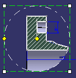
Click to validate the profile.
You can see that the view has been
clipped.
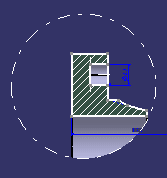
Right-click the clipped view in the specification tree or geometry and select Clipping > Modify Clipping.
The manipulators of the clipped profile are activated.
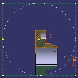
You can now reframe, resize and/or move the clipping frame according to your design needs:
- To manipulate the control points: drag the yellow manipulators.
- To resize the profile: drag the white manipulators.
- To move the entire profile: drag the frame itself using one of its
green dotted lines.
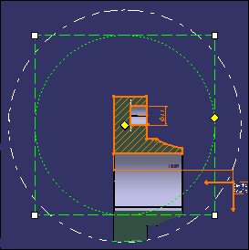
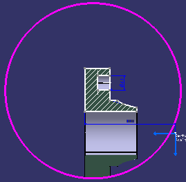
For example, drag the white manipulators to resize the profile. The green dotted
circular profile shows the clipping that will be obtained after the
manipulation.
Additionally, to change the color and linetype of the clipping
outline, right-click the view and select Properties >
Visualization tab, Clipping Outline area.
Right-click the clipped view in the specification tree or geometry,
and select Clipping > Unclip View to unclip the
existing profile.
Select Clipping > Replace Clipping from the
contextual menu to replace the existing clipping view.
The previous clipping is removed and a new clipping can be defined
in the same way as when using the Clip View
command. The graphic properties of the replaced profile are applied
to the newly defined clipping profile.