View Dress-up Parameters | ||||
|
| |||
Operators
You can configure parameters for section, detail, break and breakout.
Section
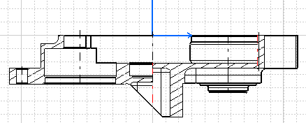
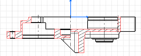
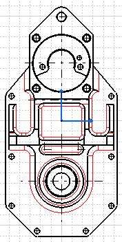
In the image below, the section profile parameter is displayed in red.
| Parameters | Value | Description |
|---|---|---|
|
Section > Visible |
yes/no |
Specifies whether or not the section profile should be visible. |
|
Section > Color |
color |
Determines the color of the section profile. |
|
Section > Linetype |
integer |
Determines the linetype used for the section profile. |
|
Section > Thickness |
integer |
Determines the line thickness used for the section profile. |
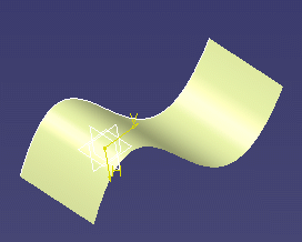
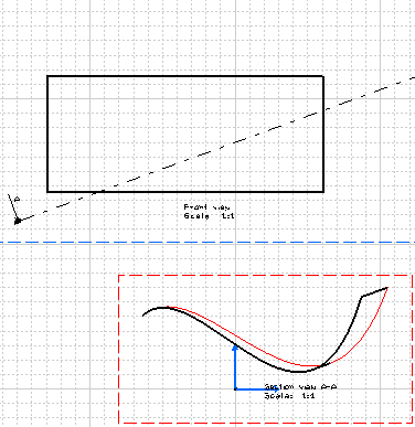
Skin Section
|
Parameter Name |
Value |
Description |
|---|---|---|
|
Section > SkinSection > Color |
color |
Determines the color of the skin section profile. |
|
Section > SkinSection > Linetype |
integer |
Determines the linetype used for the skin section profile. |
|
Section > SkinSection > Thickness |
integer |
Determines the line thickness used for the skin section profile. |
Solid Section
|
Parameter Name |
Value |
Description |
|---|---|---|
|
Section > SolidSection > Color |
color |
Determines the color of the solid section profile. |
|
Section > SolidSection > Linetype |
integer |
Determines the linetype used for the solid section profile. |
|
Section > SolidSection > Thickness |
integer |
Determines the line thickness used for the solid section profile. |
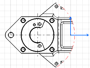
Detail
|
Parameter Name |
Value |
Description |
|---|---|---|
|
Detail > Visible |
yes/no |
Specifies whether or not the detail profile should be visible. |
|
Detail > Color |
color |
Determines the color of the detail profile |
|
Detail > Linetype |
integer |
Determines the linetype used for the detail profile. |
|
Detail > Thickness |
integer |
Determines the line thickness used for the detail profile. |
Break
|
Parameter Name |
Value |
Description |
|---|---|---|
|
Break > Visible |
yes/no |
Specifies whether or not the break profile should be visible. |
|
Break > Color |
color |
Determines the color of the break profile |
|
Break > Linetype |
integer |
Determines the linetype used for the break profile. |
|
Break > Thickness |
integer |
Determines the line thickness used for the break profile. |
Note: all parameters also apply to CGR, Approximate and Raster view types.
Breakout
|
Parameter Name |
Value |
Description |
|---|---|---|
|
Breakout > Visible |
yes/no |
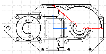
Specifies whether or not the breakout profile should be visible. |
|
Breakout > Color |
color |
Determines the color of the breakout profile. |
|
Breakout > Linetype |
integer |
Determines the linetype used for the breakout profile. |
|
Breakout > Thickness |
integer |
Determines the line thickness used for the breakout profile. |
![]()
3DInheritance
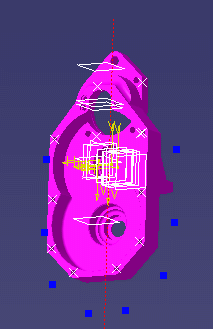
You can configure 3DInheritance parameters for wireframe, solid and 3Dpoints.
Wireframe
|
Parameter Name |
Value |
Description |
|---|---|---|
|
Wireframe > Color |
color |
Specifies whether wireframe color should be inherited from 3D. |
|
Wireframe > Linetype |
integer |
Specifies whether wireframe linetype should be inherited from 3D. |
|
Wireframe > Thickness |
integer |
Specifies whether wireframe thickness should be inherited from 3D. |
Solid
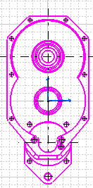
|
Parameter Name |
Value |
Description |
|---|---|---|
|
Solid > Color |
color |
Specifies whether solid color should be inherited from 3D. |
|
Solid > Linetype |
integer |
Specifies whether solid linetype should be inherited from 3D. |
|
Solid > Thickness |
integer |
Specifies whether solid thickness should be inherited from 3D. |
Note: all parameters also apply to Raster view types.
3DPoints

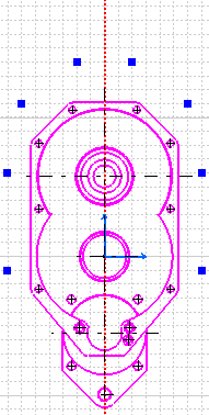
|
Parameter Name |
Value |
Description |
|---|---|---|
|
3DPoints > Color |
color |
Specifies whether 3D points color should be inherited from 3D. |
|
3DPoints > Linetype |
integer |
Specifies whether 3D points linetype should be inherited from 3D. |
|
3DPoints > Thickness |
integer |
Specifies whether 3D points thickness should be inherited from 3D. |
![]()
GeneratedGeometry
You can configure GeneratedGeometry parameters for vivid edges, hidden edges, fillets, wireframe and 3Dpoints.
Vivid Edges
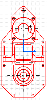
|
Parameter Name |
Value |
Description |
|---|---|---|
|
VividEdges > Color |
color |
Determines the color of vivid edges. |
|
VividEdges > Linetype |
integer |
Determines the linetype used for vivid edges. |
|
VividEdges > Thickness |
integer |
Determines the line thickness used for vivid edges. |
Note: all parameters apply to CGR and Approximate view types.
Hidden Edges
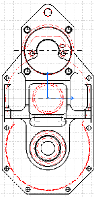
|
Parameter Name |
Value |
Description |
|---|---|---|
|
HiddenEdges > Color |
color |
Determines the color of hidden edges. |
|
HiddenEdges > Linetype |
integer |
Determines the linetype used for hidden edges. |
|
HiddenEdges > Thickness |
integer |
Determines the line thickness used for hidden edges. |
Note: all parameters apply to CGR and Approximate view types.
Fillets
|
Parameter Name |
Value |
Description |
|---|---|---|
|
Fillets > Color |
color |
Determines the color of fillets. |
|
Fillets > Linetype |
integer |
Determines the linetype used for fillets. |
|
Fillets > Thickness |
integer |
Determines the line thickness used for fillets. |

