Click Measure Probe  .
.
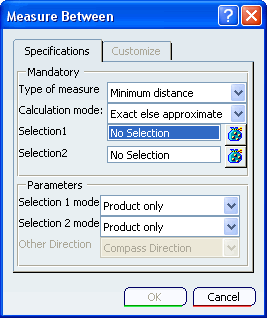
The Measure Between dialog box appears:

Select the Type of measure to track in the probe:
-
Minimum distance: Tracks the minimum distance or angle
between two geometric entities.
- Measure along a direction: Tracks the distance traveled
by a geometric entity along a specific direction.
Kinematics measure probes use all calculation modes: Exact ,
Exact else approximate or Approximate. Select
the calculation mode:
Exact else approximate (default), that measures exact data and, wherever possible, gives true values. If exact values cannot be measured, approximate values are given.
- Exact, that measures exact data, and gives true values.
- Approximate, that measures tessellated objects and gives approximate values (identified by a ~ sign).
All the geometric entities for the model are loaded automatically in the current session.
Select the two geometric entities for the probe from the 3D or
from the specification tree (the second geometric entity is ignored
if you are creating a Measure along a direction probe).
The selected geometric entities
are highlighted both in the 3D and in the specification tree as you hover over them.
If you are creating a Measure along a direction probe,
specify the measurement direction in the Other Direction
field.
To determine the types of values that are measured by the probe,
select the Customize tab. See VPM Digital Navigation User’s Guide: Customizing Measures for more information.
You can preview the measure probe in the 3D as you are creating it.
Click OK to save the measure probe and to close the
Measure Between dialog box.
You can preview the probe without saving results by running a
simulation preview (see Running the Preview); the probe values are displayed on the
mechanism as you step through the preview.