Diagnosing Computation Incidents | |||||
|
| ||||
To access the computation report, select one of the following:
- If you executed a kinematics simulation, click Incident Diagnosis
 or double-click the diagnosis directly in the specification tree.
The Incident Diagnosis dialog box appears.
- If you preview a kinematics scenario, animate a mechanism, or record an excitation, click
 .
. The Messages Reporting immersive dialog box appears.
If an incident or warning is detected, a dialog box provides you with detailed messages that describe the cause of the incidents or warnings. The computation report also appears in the specification tree under the result of scenario and is stored with the simulation when you propagate the kinematics scenario.
- If you executed a kinematics simulation, click Incident Diagnosis
![]()
Examples of Incidents and Warnings
Three types of incidents or warnings can be detected by the Kinematics solver:
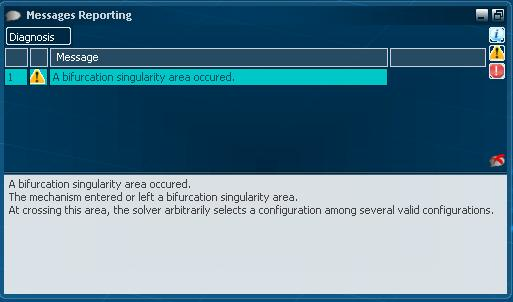
- Bifurcation Singularity Area Detection
- If a bifurcation singularity area is detected, the following message is displayed:
A bifurcation singularity area was occurred.
The mechanism entered or left a bifurcation singularity area.
At crossing this area, the solver arbitrarily selects a configuration
among several valid configurations.
- Engineering Connection Limits Reached
- If the kinematics solver reaches an upper or lower limit for a command or for any controlled value that belongs to an engineering connection, the following message is displayed:
The upper limit 20mm for Revolute.1 is reached.
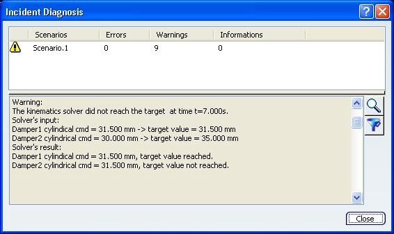
- Target Value Not Reached by the Kinematics Solver
- If the kinematics solver did not reach the target value, the following message appears:
The kinematics solver did not reach the target.
Solver's input:
Command 1 = 5mm -> Target value = 10mm.
Command 2 = 0mm -> Target value = 20mm.
Command 3 = 0mm, free.
Solver's result:
Command 1 = 7mm, Target value not reached.
Command 2 = 20mm, Target value reached.
Command 3 = 0mm, free.
Note: When an incident or a warning is detected when running the preview or simulating and generating results, a time value is added to the initial message.
The kinematics solver did not reach the target at t=5s.