More about Singularities | ||||
|
| |||
The Kinematics solver detects singularities directly (bifurcation singularity) and indirectly (lock-up singularity). Messages related to singularities are displayed in the computation report using the Incident Diagnosis function. Two singularity types are described.
- Bifurcation Singularity
- A bifurcation singularity occurs when multiple mechanism configurations are possible for the same command value. A bifurcation singularity can be illustrated with the following mechanism's configuration. Consider a parallelogram four-bar linkage with two pairs of equal-length members. The fourth bar does not appear in the figure, it is a construction line that links the anchor points.
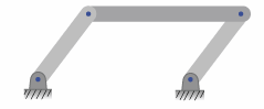
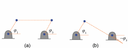
The four bars are aligned along the same line. If body 1 is driven in the positive direction from the flat configuration, two types of motions are possible and equivalent (a) and (b).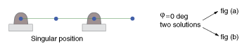
- The kinematics solver's message that corresponds to this configuration is expressed as follows:
A bifurcation singularity area occurred.
The mechanism entered or left a bifurcation singularity area.
At crossing this area, the solver arbitrarily selects a configuration
among several valid configurations.
The figure below describes how the bifurcation singularity area is detected by the kinematics solver. The bifurcation singularity occurs at the position marked 0, which lies within a small range of values known as the singularity area.(
 ). The kinematics solver's message appears when the mechanism enters or leaves a singularity area .
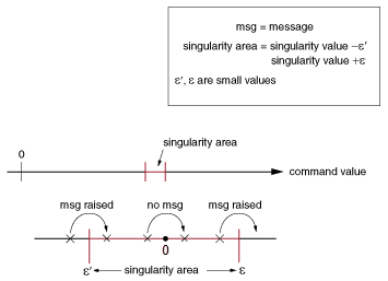
- Lock-up Singularity
- In a lock-up singularity some positions cannot be reached.
Consider a slider-crank mechanism; in the following configuration the mechanism is not locked, the mechanism is free to slide back and forth. The angle value, marked Theta
 in the figure, can be increased or decreased. The target value for Theta is 90°.
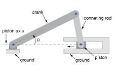
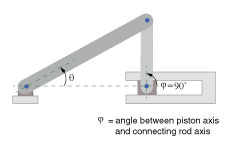
At lock-up point = 90°, the mechanism is blocked; the angle value (marked in the figure) can no longer be increased. The kinematics solver's message that corresponds to this configuration is expressed as follows:
The target value is not reached.
The kinematics solver failed to reach the target value.