Dimension Along an Entire Axis
You can siez the surface along an entire axis.
Click
Dimension  . . Select a surface. The dimensions of the entire meshed surface is displayed.
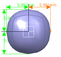
The dimensions of the entire meshed surface is displayed.
A Tools Palette is also displayed:

The following icons let you:
 define
the type of dimensioning transformation. There is one button for
all the three different states. A click on the deformation type
icon modifies its state: define
the type of dimensioning transformation. There is one button for
all the three different states. A click on the deformation type
icon modifies its state:
-
 1D transformation: the vertices move
along the direction of the selected dimension. 1D transformation: the vertices move
along the direction of the selected dimension.
-
 2D transformation: the
vertices move along the two displayed directions. 2D transformation: the
vertices move along the two displayed directions.
-
 3D transformation: the
vertices move along the three displayed
directions. 3D transformation: the
vertices move along the three displayed
directions.
-
automatically change the view point to the closest
view plane of the axis system.
-
 modifies the origin and orientation of the compass to define
new axis system. The compass definition options (reset,
translation, rotation, pick geometry, edition panel, attenuation,
selection filters) which are available in the Tools Palette define
the new position and orientation of the axis system. For more
information, refer to Managing the Compass.
Select 2D transformation. Click
the dimension to modify it. The Dimension Definition dialog box is
displayed.
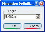
Enter the value or use the spinners to change the
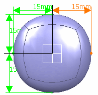
value. For instance, enter 15. Click OK.
The vertices of the subdivision surface are modified depending on the
type of transformation.

Dimension Along an Half Axis
You can siez the surface along an half axis.
The 3D shape must have at least three vertices on each axis, so that the
axis can be divided into two. If there is of insufficient number of
vertices, this capability does not work and dimensioning functions for the
entire axis.
Click
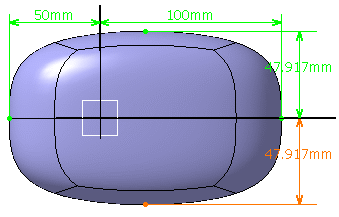
Dimension  . . Select a surface. The dimensions of the entire meshed surface is displayed:
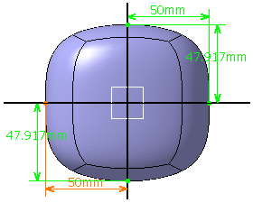
Click 1D transformation
 and Half Axis Deformation Mode in the Tools Palette.
 Click the dimension to modify it. Here, we selected the
50mm dimension. The Dimension Definition dialog box is displayed.
Enter the value or use the spinners to change the value.
Here, we entered 100mm. Click OK. The vertices of the subdivision surface are modified along half the
axis without moving or modifying dimension along other axis:
|
![]()


