More about Dimensioning Subdivisions | ||||
|
| |||
General Information
This sub-topic gives you general information about dimensions, their display and their behavior when modified.
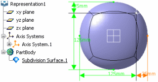
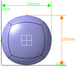
- The default dimensions are displayed in the two most seen directions.
- When a dimension is modified, all the dimensions along that direction are also modified.
- If the view point is modified, the displayed dimensions may change too.
- Deformations are not commutative: if you change the dimension and go back to the original dimension, you may not get the exact same shape.
- The Dimension capability works with a precision lower than 0.1 mm. If the precision level exceeds this limit, a warning message is issued.
- The display of the projection plane depends on the option selected
for transparency in Tools > Options > Display >
Performance tab, Transparency Quality area, that is either
Low (Screen Door) or High (Alpha
Blending).
For more information on these options, refer to
CATIA Infrastructure User's Guide: Customizing: Customizing settings: Performance .
![]()
Dimensions and Axis Systems
This sub-topic explains the role of the axis system when dimensioning a subdivision.
- The dimensions are computed from the current axis system (i.e. either the default axis system of the part or the one you have selected) to the extreme end of the surface.
- Before entering the Dimension command, you can select an already existing axis system, which is used as the reference to display the dimension from this axis. Any modification of the dimension is in reference with this axis.

- You can define an axis system during the command using the compass: dimensions are then recomputed from this axis system.
