Creating Thread Dimensions | |||||
|
| ||||
Click Thread Dimension
 in the Annotations toolbar (Dimensions sub-toolbar).
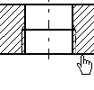
In the front view, select the thread to be dimensioned. The Tools Palette toolbar is displayed, to let you select the dimension representation.

In this case click the thread diameter, and the dimension is created.
Depending on whether the thread has been automatically or manually created and/or standard has been specified in your 3D document, you will have following cases:
Automatically created 3D Thread without a standard Automatically created 3D Thread with a standard Created 2D Thread with no association to 3D Thread The dimension is created from a 3D thread and this 3D thread has no standard. The dimension is created from a 3D thread and this 3D thread has a standard. The dimension is created from a 2D thread (no 3D thread is associated to this 2D thread) or from two parallel lines. The value of the thread diameter dimension will be the 3D thread diameter value and a diameter symbol will be set as a prefix on the dimension. This prefix can be edited and will be not deleted or replaced at dimension update. The value of the thread diameter dimension will be the description of this 3D thread (the prefix of the dimension cannot be defined). The value of the thread dimension is the diameter of the 2D thread (top view) or the distance between the lines (side view) and a prefix M is added to dimension value. The thread diameter will appear as:

The thread diameter will appear as:

The thread diameter will appear as:

On selecting Force Horizontal Dimension in View the dimension would appear as: Dimension1.object > Dimension Representation > Force Horizontal Dimension in View.

On selecting Force Vertical Dimension in View the dimension would appear as:

Click Thread Dimension
 again.
In the section view, select the two lines representing the thread to be dimensioned.

Two thread dimensions appear, representing the thread diameter as well as the thread depth.


Notes:
- The dimensions are created as feature dimension. If the Activate analysis display mode check box is selected in Tools > Options > Mechanical > Drafting > Dimension tab, these dimensions are therefore displayed using the color defined for Technological feature dimensions in the Types and colors dialog box (click the Types and colors... button in the Analysis Display Mode area).
- In top views, you can modify the orientation of threads dimensions.
Important: When a thread diameter dimension is created from a 3D thread, note that: - if this 3D thread has a standard, then:
- the value of dimension is the description of this 3D thread
- the prefix of the dimension cannot be defined (from Tools > Options > Mechanical > Drafting > Dimension Texts tab).
- if this 3D thread has no standard, then:
- the value dimension is the 3D thread diameter value
- a diameter symbol is set as a prefix on the dimension. In this case this prefix can be edited (from Tools > Options > Mechanical > Drafting > Dimension Texts tab).
Notes:
- If the 3D thread has a standard description, the value of the associated thread diameter dimension is always the Thread Description (Hole Definition dialog box, Thread Definition field) as of the 3D thread. The dimension value cannot display the diameter of the 3D thread in side as in top view (except if you add a fake value).
- Thread dimensions created on top views are technological features now, so they cannot be re-routed.
- Thread dimension on top view will stay associative to 3D thread even though 2D thread is deleted.
Important: When clearing the Thread check box in the Properties dialog box (available via Edit > Properties), the thread dimension loses its associativity. It appears as being not up-to-date using the color defined for Not up-to-date dimensions in the Types and color dialog box. If you re-select the Thread option from the Properties dialog box, it does not make the thread dimension associative again: it still appears as not up-to-date. You need to re-create the dimension.