Click Dimension
 in the Annotations toolbar (Dimensions sub-toolbar).
In the Tools Palette, click Intersection
Point Detection
 .
Refer to
Creating Dimensions between Intersection Points for more information
about this functionality. .
Refer to
Creating Dimensions between Intersection Points for more information
about this functionality.
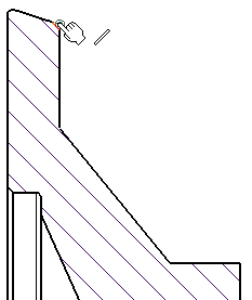
Click the first element, in this case, an intersection
point.

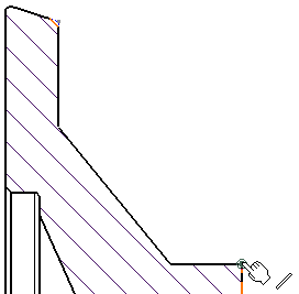
Click the second element.

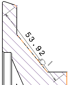
The dimension to be created is previewed.
In the Tools Palette, click Force dimension
along a direction
 . .
Several options are then displayed in the Tools Palette:
-

Dimension along a direction creates the dimension
using a linear element (line, axis line, center line) as
the reference direction, or using an angle to define the
reference direction relatively to a linear element. In the
latter case, key in a value in the Angle field.
-

Dimension perpendicular to a direction creates
the dimension perpendicularly to a linear element.
-

Dimension along a fixed angle in view creates
the dimension using a fixed angle in the view. In this case,
key in a value in the Angle field.
Note that such a dimension follows the view
rotation. Thus, a dimension line with a 30 deg angle in
a view which is set at 45 deg (relatively to the sheet)
will be equivalent to a dimension line with a 75 deg angle
relatively to the sheet.
Click Dimension along a direction
 .
For the purpose of this scenario, leave the Angle field set
to 0 deg. .
For the purpose of this scenario, leave the Angle field set
to 0 deg.
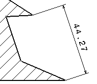
Select a linear element to use as the reference direction.
Once created, the dimension will be associative to this element.

The dimension is updated so as to measure the distance
between the selected points once projected onto the reference direction.
Drag the mouse to position the dimension as wanted.
Click to validate the dimension creation.

|