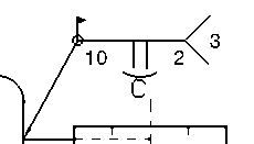
Creating a Welding Symbol | |||||
|
| ||||
Click Welding Symbol
 in the Annotations toolbar (Symbols sub-toolbar).
Select one or possibly two elements defining the weld (this will determine the position of the leader anchor point), and then click to validate. The welding leader will appear.
Important: In the case of a Generative Drafting view associative to a weld specification originally defined in the Weld Design workbench, select the weld representation. 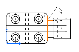
Move the cursor to position the welding symbol and then click at the chosen location.
The Welding creation dialog box is displayed.
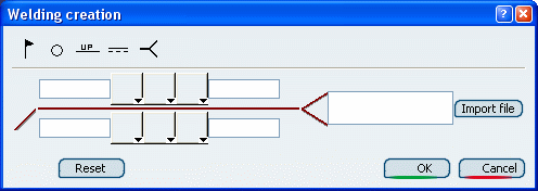
Important: In the case of a Generative Drafting view associative to a weld specification originally defined in the Weld Design workbench, this dialog box is pre-filled in accordance with the 3D specification. The welding symbol will be created associatively to the 3D specification. In this case, you will not be able to change the parameters in the dialog box. Refer to More About Welding Symbols for more information. Type the desired values in the upper and/or lower field(s).
Click the symbol buttons to choose the welding symbol, complementary symbols and/or finish symbols.
Tip: The welding symbols available depend on your standard. If you want to add complementary indications like a field weld or a weld tail, for example, click the appropriate button.
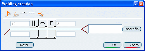
Click OK.
The welding symbol is created.
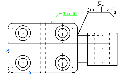
If needed, modify the welding symbol position by dragging it to the required location.
Double-click the welding symbol to edit it, and change the weld text side for example by clicking the Up/Down switch button.
