More About Welding Symbols | ||||
|
| |||
Welding symbols
This sub-topic provides more information about how to define primary welding symbol, complementary symbol and finish symbol to create the welding symbol.
You can add the following welding symbols according to the dedicated standard.
Weld type
| Name | AWS | ISO | JIS |
|---|---|---|---|
| Square butt weld |  |
|
|
| Singe V butt weld |  |
|
|
| Single bevel butt weld |  |
|
|
| Flare V butt weld | NA |  |
NA |
| Flare bevel butt weld |  |
 |
|
| Single U butt weld |  |
|
|
| Single J butt weld |  |
|
|
| Fillet weld |  |
|
|
| Spot weld |  |
|
or  |
| Back weld |  |
|
|
| Steep-flanked single-bevel butt weld | NA |  |
NA |
| Steep-flanked single-V weld | NA |  |
NA |
| Plug weld |  |
|
|
| Removable backing strip used | NA |  |
NA |
| Permanent backing strip used | NA |  |
NA |
| Surfacing weld |  |
|
|
| V flare weld |  |
|
|
| Seam weld |  |
|
|
| Edge weld |  |
 |
|
| Surface Joint weld | NA |  |
|
| Inclined Joint weld | NA |  |
|
| Corner Flange weld |  |
NA | |
| Flare V weld |  |
NA | |
| Melt Thru weld |  |
NA | NA |
| Scarf weld |  |
NA | NA |
| Stud weld |  |
NA | NA |
Complementary symbols
| Name | AWS | ISO | JIS |
|---|---|---|---|
| Weld with flat face |  |
|
|
| Weld with convex face |  |
|
|
| Weld with concave face |  |
|
|
| Flush finished weld | NA |  |
NA |
| Fillet weld with smooth blended face | NA |  |
NA |


![]()
Miscellaneous information
This sub-topic provides miscellaneous information about welding symbols.
- If you have selected the Use style values to create new objects option in Tools > Options > Mechanical > Drafting > Administration tab, the Welding creation dialog box is pre-filled with custom style values (as defined in the Standards Editor). In this case, Properties toolbars and the Tools Palette are disabled during the creation of the welding symbol. On the other hand, if you have not selected this option, the Welding creation dialog box is pre-filled with the last entered values (if any). In this case, Properties toolbars and the Tools Palette are active during the creation of the welding symbol.
- You can reset the current style values in the Welding creation dialog box at any time using the Reset button.
- You can close the tail (reference) using a rectangle variable-size frame
 .
For more information about adding frames, refer to
Adding Frames or Sub-Frames.
.
For more information about adding frames, refer to
Adding Frames or Sub-Frames.
- At any time, you can modify the welding symbol. To do this, double-click the welding symbol to be modified and enter the modifications in the displayed dialog box.
![]()
Associativity to 3D Welds
In a Generative Drafting context, Generative View Styles (GVS) enable you to specify whether weld features defined in 3D (in the Weld Design workbench) are to be represented symbolically in views.
For more information, refer to
Generative Drafting User's Guide: Administration: Setting General Generative View Style Parameters: Generate Parameters.
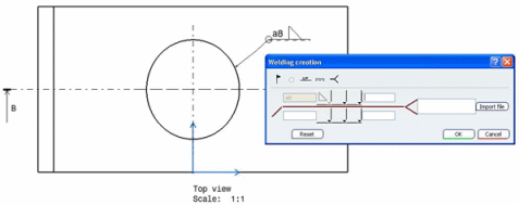
If you create a view containing a weld symbolic representation using GVS, you can then create a welding symbol that will be associative to the 3D weld specification, by selecting either the side or the top representation of weld seams (even if they are hidden by other geometry). In this case, the Welding Creation dialog box will be pre-filled with the following information:
- Weld type (simple or double information)
- Weld length
- Weld thickness
- "Weld-all-around" symbol
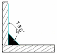
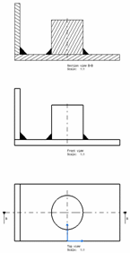
The image below shows a welding symbol created on the top representation of a weld seam hidden by other geometry:
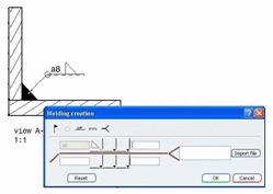
The image below shows a welding symbol created on the side representation of the weld seam:
Notes:
- When updating the drawing, if the 3D weld specification cannot be found (if it has been deleted for example), the welding symbol update fails. In this case, the welding symbol content is not modified, and it is displayed using the color specified by the Dimensions for which last update failed option in Tools > Options > Mechanical > Drafting > Display tab, in Elements Analysis area, selecting Activate elements' analysis check box, and clicking Configure . Refer to Settings Customization User's Guide: Mechanical Design Settings: Customizing Settings: Annotation and Dress-Up for more information.
- If you right-click an associative welding symbol, the Isolate and Query Object Links contextual commands are available from the contextual menu.
- You can also create dimensions on weld representations by selecting
their profile. However, such dimensions are not associative and cannot drive
the 3D. The image below shows a dimension created on the side representation
of the weld seam.